Sunday, January 22, 2017

Mitsubishi Delica: planning stage

So I've got these two curbside kits (from Aoshima) of the Mitsubishi Delica Star Wagon 4WD Super Exceed. Yes, really. From now on it will simply be the Delica. These are occasionally sighted around Vancouver as a Japanese import with right-hand drive. They are tall, narrow, tippy little things, with lots of room per square foot of roadway occupied; mechanically there is a noisy little 4 cylinder and a jacked-up 4WD chassis. I couldn't resist the opportunity to cut them up and build an 8X8 crew cab with a platform suitable for carrying the Honda S800 racer that I've already got. So fresh off the Jimney, I got out the saw blades.

First, however, I did a little planning using photos and the old-fashioned technique, literally, of cutting and pasting. (You younger folks may want to ask your Dad about 'scissors' and 'Scotch tape'. I believe the modern version is called 'photoshopping').


I came up with two versions: one with a central section from Kit 1, augmented with the ends from Kit 2; this would be about 20' at scale. The second involved splicing in the middle door from Kit 2, which would make 23' total length. I decided on the 20' version as this is plenty for the Honda to park on the rear deck while still allowing a cab of almost 10'. The picture below shows the 20' version done up as a van.


An initial design had two cabs back to back which would have been cute, but perhaps impractical... I eventually decided to go with a classic crew cab shape.


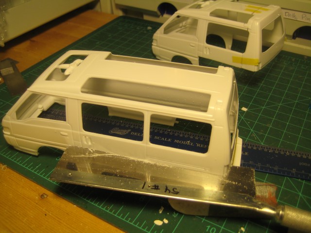
After deciding how to minimise number of cuts while maintaining some reasonable level of dimensional integrity in the various components, initial cutting went well. Here Kit 1 has gotten the chop and the rear body panel has become the cab back wall, while Kit 2 watches nervously from the back.


Next up: slice off the lower section of Kit 2. I followed the upper edge of the side molding as a convenient marker. The 54 tpi blade came in handy as did the jeweller's saw with an 0.008" wire blade.


Taping everything together reveals a few spots where putty will be needed, but overall the mockup looks good. I may hijack the front door panels from Kit 2 and use them for the opposite-side rear doors on Kit 1; the rear passengers will be sitting on a wheel well and will therefore be facing backwards, so the raised window sill will be needed to cover the roll-down window. Overall seating should be 5 people, two in front either side of the engine, and three facing back. There may be room for a couple of forward-facing jump seats, to be determined.


Of course getting chassis and interiors to line up will require some planning; but as it is a curbside, I won't bother with an engine, and the axles may or may not actually be connected to a driveshaft.

Stay tuned for more gory modeling tales. There is something cathartic about slicing stuff up...

Friday, January 20, 2017

Mosquito: Background information

As an old car mechanic, my first step on getting my hands on something obscure to (re)build is to get hold of suitable manuals. (A mechanic of old cars, or an old mechanic? No comment). In the absence of actual period manuals for the Mossie and the Merlin, I turned, as I often have in the past, to the aftermarket.


While these Haynes manuals are a little short on actual specs, such as cylinder head bolt torques or big end clearances, they do give a very nice overview of the subjects.

The Merlin is well known but its level of advancement is perhaps less so. With lots of aluminum castings and 4-valve SOHC heads, the Merlin presages modern automotive applications. In particular the bore:stroke ratio is decidedly modern at 0.90, compared to the classic Jaguar 3.4 at 0.78. (The Jag 4.2 got its added displacement from a bore increase, bringing the ratio to 0.87). One wonders why the British were so resistant to oversquare motors when Ferrari had been building the classic 3-litre at a ratio of 1.24, and beating the C and D-Types mercilessly as a result. The run of Jag successes at Le Mans in the 1950's was mainly due to Enzo being leery of disc brakes, because the Jags certainly couldn't keep up with the Ferrari 250s on the straights. And once Enzo adopted IRS and discs, it was pretty much all over for Jag.

Now that I have ticked off all the Jag fans out there, on to the Mosquito and the revolutionary plywood construction methods involved.

I haven't digested the whole thing yet, but some initial impressions are revealing.

The fuselage was built in two long halves, of balsa wood sandwiched between two layers of Canadian birch. Glues were similar to the ones still in use today, namely urea formaldehyde formulations. Total wall thickness was only 7/16"! Of course load bearing points were reinforced, and it seems the internal bulkheads were aluminum. The construction method allowed all the wiring, hydraulics and control bits to be put in before the two halves were glued and screwed together.

Wings and tail were also wood, with wooden spars covered with a plywood sheet. The wing was built as a single big piece, and is modeled this way in the Airfix kit. The completed fuselage was lowered onto the wing, the two pieces glued and screwed together, and the whole thing covered with fabric and airplane dope to seal it.

One big advantage of this approach was that precious reserves of aluminum were stretched, but another was that a large number of British furniture makers and coach builders could make the basic structure, freeing up existing metalworking industries for other war-time uses. Although I don't have numbers at the moment, presumably the power to weight ratio was better than similar all-metal planes, contributing to the Mossie's reputation for speed and manoeuverability.

Stay tuned, there is more to come, starting with the actual first gluing of parts.

Thursday, January 19, 2017

Suzuki Jimney: Completed

So the first kit completed for 2017 is a quick-and-dirty kitbash, involving a 1.9 litre Opel 4-cylinder with a scratch-built intake manifold designed to take a blower from the parts bin, all shoehorned into a Hasegawa curbside kit of a Suzuki Jimney mini 4X4. Why an Opel 1.9, you ask? Mainly because this was the only 4 cylinder I had available. A Honda VTEC motor would perhaps have been more appropriate, had there been one handy. Plan B would have been to cut a V8 in half, leading to either a V4 or a slant 4. Maybe the next one...


As the kit was curbside, this required removing the hood and fabricating a firewall from sheet styrene. The header tank, heater motor ductwork and master cylinder all came from the parts bin. Plug wires and cable ties came from a Model Car Garage package, also from the parts bin.


I also cut up a side pipe for the exhaust. The sewer-pipe diameter is probably overkill for the 1.9, even with a blower, but it looks fine, and exits on the passenger side (the cab is right-hand drive). The wheels and Goodyear Wrangler AT truck tires also came from the parts bin, as the stock wheels were weeny little things. (The spare, attached to the rear door, is stock). They complement the extra ride height nicely.


Years ago I shoehorned a complete 3-litre twin-turbo V6 and drivetrain from a Dodge Stealth into another Suzuki, this one a Samurai. Also AWD, the purpose here was a street cruiser and pro-stock machine, with mid-engine setup, blanked-off headlamps and cut-back windshield. The body also got a pretty serious section, and the cockpit got moved forward a substantial amount to clear the turbos. It looks good next to the jacked-up, go-anywhere Jimney. I just need to get the dust off it...


Ideally the Samurai needs bigger fender flares; technically it works but the body section is probably too aggressive for replication at 1:1; as well the cockpit was moved forward without stretching the wheelbase, so legroom around the pedals is non-existent. 


In any case the Jimney is a neat addition to the Japanese shelf. So what's next: back to the serious stuff, or more kitbashing? Stay tuned!

Wednesday, January 18, 2017

Suzuki Jimney hot rod: Chassis

I've been away from this for a while, but made progress today on the chassis and engine installation.

The Jimney comes with two suspension choices: normal and lifted. With the oil pan from the Opel 1.9 intruding into space occupied by the front axle, I had to go for a third option: extra lifted. The big truck tires and steel wheels, from the parts bin, will fit much better in the wheel wells than the weeny little things in the kit. Maybe I can find some dog dish hubcaps.


The supercharger fits nicely, and the engine now has plug wires from Model Car Garage. Let's assume 300 HP from the blown 1.9; the Jimney has decals proclaiming the presence of a turbo, but given the base engine is only 660 cc, it is unlikely to be much over 100 HP. Let's hope the transfer case can take it!


The front of the engine compartment may even have room for a radiator and header tank ahead of the blower drive. I'll have to scratch build a firewall; there is no point in putting in a master cylinder as it will be hidden by the blower (the dash is set up for right-hand drive). The only remaining item is an exhaust pipe; I found a laker-type sidepipe in the parts bin that will fit nicely along the left side rocker panel once it is all in place -- just a bit of cutting needed to make it fit.


Paint scheme at this point is glossy orange on the lower body, with flat black above. Wheels will probably be flat black as well. Stay tuned.

Saturday, January 7, 2017

DH Mosquito FB.VI: opening the box

Welcome to my new blog, which is meant to chronicle my adventures with the Airfix 1/24 scale model of the De Havilland Mosquito FB.VI fighter bomber. If I survive the Mosquito, there could be other planes here later.

I introduced this topic in a post in my other modeling blog, here, where I have been posting about adventures in the automotive modeling world.  I mentioned my interest in the Mosquito which arises from its unique construction methods (the fuselage was largely of plywood). Today we'll begin with the ceremonial opening of the box.


And what a box it is. The dimensions are dictated by the wingspan, which will be something like 26" at scale. The box overall is 27" x 16" x 7". Taking out the various sprues, it looks like this:

The fuselage, at about 18" long, takes up an entire sprue. Nothing about it points to the fact it was made of plywood.


Next is the wing. Apparently this was also built of plywood. The photo shows a second sprue with a range of flaps and things -- I am sure there are proper aeronautical terms for all this! The instruction booklet unfortunately does not name any of the components, unlike the good old AMT instruction sheets.


More flaps, rudders, nacelles and other unidentified bits...


Next we have a number of sprues that are duplicated. The obvious one is the two Rolls-Royce motors; it sure would be nice to have a couple of spares for kitbashing. The second pair of duplicated sprues models engine nacelles and landing gear, while the last pair models what looks suspiciously like armaments.


Random stuff at the end includes a black sprue with two plastic tires that clearly need air, a clear canopy, and a pair of sprues with the rest of the engine nacelles and the propellers. I took the advice of the IPMS site and ordered the Scale Aircraft Conversions landing gear, which is made of spun cast white metal; it seems the styrene bits are particularly fragile. The ISPM site generally seems to be an excellent source for aircraft modellers, with a very through review of this kit here.


The final picture shows the crew, in two poses: seated at the controls, or standing next to the ladder.


Some other random comments:
  • Paints are called out using Humbrol numbers. Fair enough, Humbrol and Airfix are owned by the same company, but nowhere is there a list showing what colour Humbrol 11 is. (It's silver). Fortunately there are correspondence charts out there, for instance here. I sense the ISPM will become a good friend of mine going forward... the little Humbrol paint pots look like a pain to keep sealed, unlike the screwcaps on Model Master or Tamiya paints.
  • There are 236 steps in the 55-page manual, and some need to be repeated twice. For example, the motors are steps 69 to 100.
  • The level of detail is high, judging by the motors.
So where to start? Assembly starts with the cockpit. Stay tuned...

Thursday, January 5, 2017

1/43 BRM H16: overview

I described this kit in my last post... and yes, it is at 1/43 scale, not 1/24 (or 1/25). My excuse is that it is a fascinating little car, and unavailable in 1/24. Go ahead, sue me.


The kit is mostly spun-cast white metal, with a small photo-etched sheet (heck, it's 1/43, everything is small), machined aluminum rims, rubber tires and a few other little bits in a series of heat-sealed bags. There are no resin or styrene bits. I opened the two little Zip-Loc baggies and spilled all the white metal bits out onto my work surface.


In the photo: engine bits to the right front, chassis and wheels left front, cockpit stuff centre rear, and odds & ends in the middle. I rebagged it all in some semblance of order.

The main engine components appear well defined, although I am sure the usual issues will arise around dowel and socket joints -- the dowels will need some careful filing to get rid of scarf without damaging the dowel, and the sockets will need drilling to clean them out.


The instructions seem reasonable, and the level of detail, while high, doesn't look excessive. Still the 4X magnifying glass will get some use, as will the tweezers and the detail glue applicator. To be continued ...

Wednesday, January 4, 2017

And now for some more completely different stuff

Regular readers (if any) will have noticed that the name of this blog is http://24th-scale.blogspot.com. The fact is that 1/24 (and its close relative, 1/25) is a popular scale for cars, because it is a nice compromise between maximising detail and minimising shelf space. And as a former foreign auto mechanic, good automotive subjects are of interest to me. But nowhere did I claim I would only discuss automotive projects. And I have had plenty to say about resin, so I am not limiting myself to styrene either.


A while back I mentioned the acquisition of the wooden 1949 Chris Craft runabout. I have added to this the recently-released 1959 Century Coronado from Lindberg. The parts bin will come in handy here, both for the Coronado which has a poorly reproduced V8 of some sort, and for the Chris Craft, which has no motor at all. A Thunderbird Tri-Power for the Coronado and a flathead for the Chris Craft are in the wings. Both will need trailers.


I also got my hands on a Zundapp KS 750 motorcycle, modeled in 1/24 by the Japanese company Asuka. Bikes tend to be either 1/12, allowing more detail for the same shelf space as a car at 1/24, or 1/35 for the military modellers who would normally be interested in something like this. The bike was used by the German army in 1941-43, and looks like a vintage BMW with an opposed twin and shaft drive. There appear to be two complete kits in the box, perhaps a mistake; the second complete set of sprues is fully chromed. It also appears that there is a version with a side car, which I would have ordered if I had known it was available.

Moving on from boats and bikes, I got brave and bought the Airfix 1/24 scale model of the De Havilland Mosquito. There aren't a lot of planes modeled in 1/24 because they are so big; the Mosquito in real life has something like a 54 foot wingspan, meaning 26" at scale, so it will need to be hung from the wall or ceiling once complete because none of my display cabinets come close to fitting it. For this reason, model airplane scales typically range from 1/48 all the way to 1/144. The kit is daunting: over 600 pieces, and the ISPM website (click here) flags that it is not for beginners. The instruction manual says it is not suitable for children under the age of 36. Months that is. Right. I'd like to see a 3-year old tackle this.


The Mosquito is of interest to me because it was made largely of plywood, which was considered at the time to be a very advanced composite material. Shortages of metals in the war years made this an interesting option, although the state of the art in phenolic resins at the time made this a very expensive option. The kit also apparently models the two Rolls Royce aero engines well. The RCAF flew these well into the late '50s, so I will look for colours of these later planes. As a side note, the people who worked on this moved on to build the Marcos car in Britain in the '50s, which also featured a plywood chassis.


I will build this at a friend's house because the household includes two young men who are actually pilots, so maybe there will be some advice as to how it is supposed to look. This project looks to be complicated enough that it merits its own blog, and I have created https://24th-scale-air.blogspot.com for this purpose. There is no content there yet, but come back soon!

Finally, heresy of heresies, I ordered a 1/43-scale kit. Yes, this goes against the fundamental mission of this blog, and represents my first foray out of the 1/24-1/25 scale world. But the kit, and the car, is unique.

I have accumulated quite a stash of MFH kits, and have been intrigued by their 1/43 kit of the BRM H16. This 3-litre F1 car, driven by the likes of Jim Clark and Graham Hill, featured a three liter, sixteen cylinder motor consisting of a pair of flat eights stacked one on top of the other and geared together, hence the H16 designation. As the common gear train that connects all the cranks and camshafts is in the middle of the 'block', this is arguably a set of four flat fours of 750 cc each. Intake manifolds were located, pointing outwards horizontally between the inlet and exhaust cams, there were exhaust manifolds both below and above the heads, and I am not sure where they hid the spark plugs.


Probably the only more complex motor out there is the fabled 1.5 litre flat 16 assembled by the guys at Coventry Climax in the last year of the 1.5 litre formula. Imagine 16 moped engines, of just over 90 cc each, allegedly making 180 hp at 12,000 RPM, and imagine all this going to waste a year later with the new 3-litre formula, which they knew was coming. What were they thinking?


Somewhere I recall reading that at a given bore:stroke ratio, the smart money in racing engines is on cylinders of about 375 cc each. This would apparently be a balance between lots of piston area and low piston weight on the one hand, and lots of frictional surface area due to lots of crank pins on the other. I am also guessing that gas flows in inlet and exhaust pipes are getting into pure boundary layer flow regimes as the tubes get smaller, especially at high velocities, and that this is probably not a good thing for breathing. On this score, neither the Coventry Climax motor nor the BRM motor are a success, but the Cosworth DFV 3-litre V8 fits well, as did the 3.5 litre V10 motors used in F1 up until some time ago.

In any case, the BRM kit, while in 1/43, is quite detailed and is mainly spun-cast white metal. The box is barely 6" x 3 1/2" x 2" but it looks as complicated as the Mosquito. The 4X magnifier will come in handy.

All in all it is a Good Thing that I am retired... Stay tuned!