Tuesday, December 3, 2019

Mosquito: Airframe complete

So the Port nacelle is well underway; the starboard one still needs to be started.


Meanwhile the wing and fuselage is pretty well complete. Paint includes the red and white stripe as used by Ottawa's Spartan Air Services on the tail fin.


With the wing inserted, the navigational bits can go into the back of the cockpit which is also now essentially complete.


View through the access door.


It's a monster! The 27" wingspan means it won't fit in any of my display cabinets.


Next is to finish the port nacelle and build up the starboard nacelle.


Looking for decals for the civilian high-altitude reconnaissance version with pressurised cabin as flown by Spartan Air Services in Ottawa, Canada, from about 1955 to about 1065. Seems they had 15 Mossies,,, the sheet I want is below but is too low resolution to print. Any help is appreciated!


Given I am going to skip all the armaments, the end is near. Stay tuned!

Monday, December 2, 2019

Mosquito: landing gear and cowling, test fit

Well, if I thought the cockpit and engines were going to be the most challenging parts of this build, I was wrong. Building the landing gear and fitting it, along with the Merlins, into the cowlings were not easy steps.


Along the way I found advice on the Interweb to the effect that the landing gear is fragile and should be replaced with aftermarket bits from Scale Aircraft Conversions. I acquired the bits and while the assembly so far uses the styrene bits, the white metal bits will come in handy as I have already broken a couple of styrene struts.


The aftermarket bits include relatively sturdy items such as the hydraulic cylinders, but also the finer structural bits. Sadly these are mostly bent, so best to go with the styrene initially, using the aftermarket bits only when needed.


For the purposes of test fitting everything, I have taped the landing gear in the retracted position so as to minimise breakage. I will pose it with gear down, however.


The Merlin is a tight fit, and the green structural tubing appears to not line up very well. Test fitting the second half of the cowling helps identify where everything is supposed to fit.


Landing gear won't fit through the opening, for some reason, so I'll have to be sure to put the gear down before gluing the second cowling half in place.


Fit to the wing is a challenge as well!


All coming along now. Next is final assembly which requires disassembling first as there is a bunch of piping, struts and other items to go in before closing up the cowling. The second engine and landing gear assembly should go together more easily. (Of course I have now jinxed myself...)


It's starting to look like an airplane! Stay tuned.

Tuesday, November 19, 2019

Mosquito: Twin Merlins complete

What a lovely pair of engines! Very detailed.

Engine block with supercharger and carburettor housing facing downwards at the front. The aluminum box at the back of the head is the magneto for the exhaust-side spark plugs. There is another mag on the other side; additional mags for the intake side plugs are not modeled.


Second block in preparation.


The tubular engine support structure is very delicate, and looks a bit thin given there is 1460 horsepower on tap. However there was no record of these engines ripping themselves from their mounts, so presumably it all worked out.


Some of the piping. Oil and water pipes are external in many cases.


Completed engines on their tubular supports. The first photo is the left side, which I gather is the port side. The builds diverge from here on as the radiators are built into the wing between the engine nacelles and the fuselage, so piping goes either left or right from here on. 


Starboard side. The unit to the far right is the propeller unit on its reduction gearbox. The carburettor intake is on the left side at the bottom.


The "back" end of the engines where the supercharger drive is taken off. Some piping gets connected once the engines are slipped into their nacelles. 


Water header and propeller drives at the forward end of the engine.


Bits of paint touchups are needed, but it's pretty well done by now. Lovely builds and it is too bad you can't get these for scratch building hot rods. Stay tuned!

Sunday, November 17, 2019

Mosquito: Basic wing assembly complete

Last time I posted on the de Havilland Mosquito was back in June 2017, when I completed the cockpit and glued the fuselage halves together. I dug the enormous box off the Shelf of Doom and dusted it off.


The wing was made as a single unit back in the day. In the Airfix kit, the upper surface is also a single piece and comes as part of the largest sprue I've ever seen.


Three lower sections required clamping. I will build this one as a civilian plane from the 1950's, reproducing a version flown by Spartan Air Services out of Ottawa. So there will be extra fuel tanks on the wings instead of the more usual machine guns.


What a monster ...


Next: flaps and other bits associated with the wing, then on to the twin Rolls-Royce Merlins.


Stay tuned!

Wednesday, October 30, 2019

Lotus Eleven: Chassis mods II

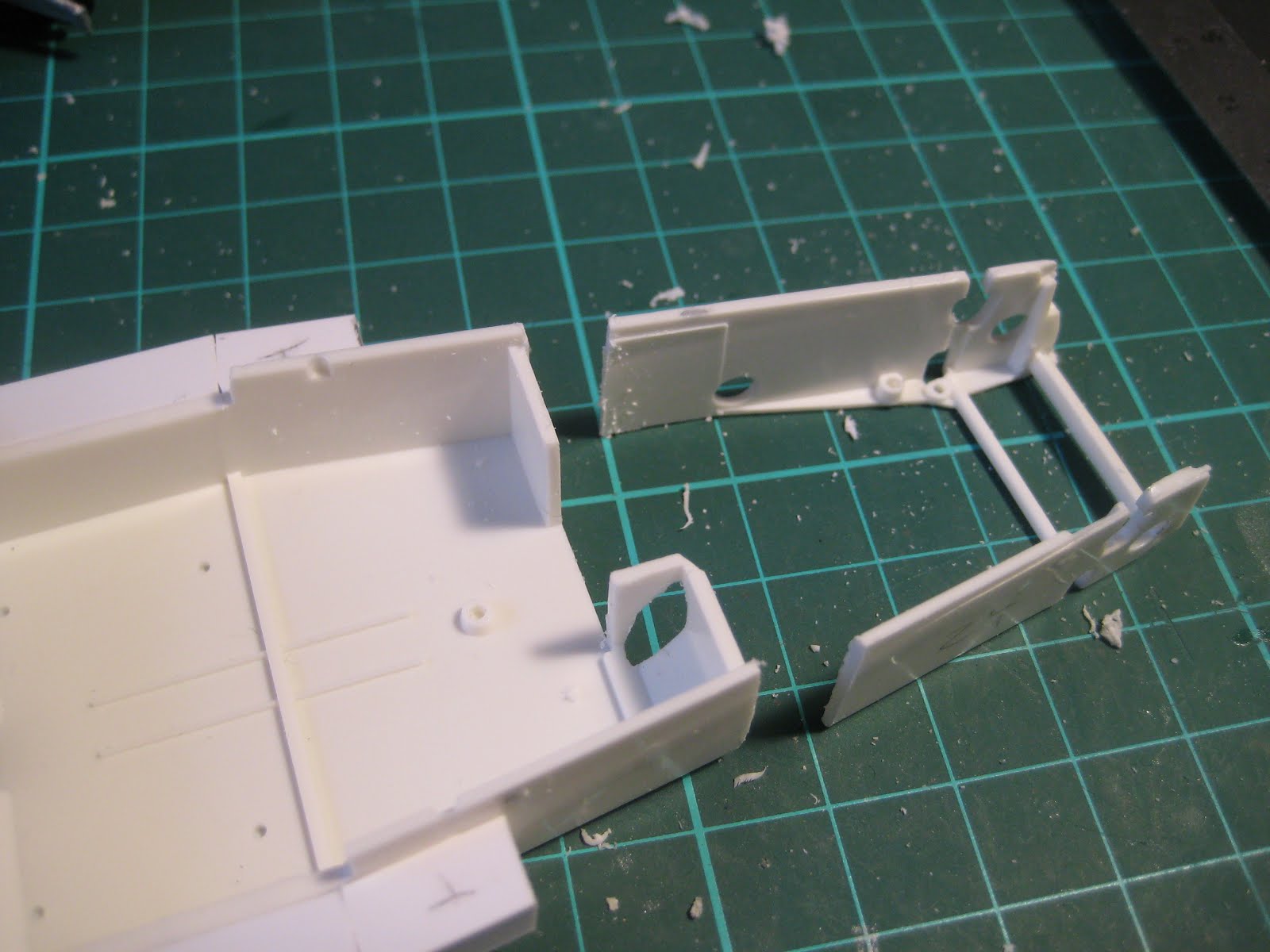
The donor chassis from Tamiya's Seven having been shortened the required 5 mm, next was to build up the chassis forward of the radiator to support the hood from the Eleven and mimic the radiator ducting needed. The Seven has a short little nose cone which will be discarded.


Styrene sheet in 0.030" thickness along with some angle iron served to rough it out. The picture shows added structure along the sides of the cockpit to mimic the full floor pan that extends, in the 1:1 Eleven, up to the door sills.


Test fits show it all lining up nicely. Other bits that have been fabricated, but not shown in the photos, include a new firewall and floor pan components from the front fender well rearwards.


The air intake is pretty small and I can imagine that, like early E-Types, it is likely to overheat in traffic or on hot days. Being British, it isn't designed for either of these conditions.


The hood will hinge on a piece of brass rod, 1/32" diameter, inserted into two short lengths of 1/16" tube. The issue will be that once the lengths of tube are glued to the hood, it's all permanent and there won't be any opportunity to remove it to fiddle.


So progress is being made and it will soon be time to start thinking about painting the chassis. Stay tuned!

Thursday, October 10, 2019

Lotus Eleven: Chassis mods

Given the inaccuracies in the Tamiya and Profil 24 kits added rather than cancelling, I had to take about 5 mm out of the Seven chassis to get it to line up under the Eleven body.


First step was to carve out the footwell to clear the starter motor Bendix and a slice of the bell housing. In real life this would interfere with the clutch pedal in a footwell that is already pretty cramped, but hey, this is 1:24, not real life. And the firewall thickness works out to over an inch at scale, where we all know it would have been 16 gauge aluminum sheet (1/16") in real life. But 16 gauge, at 1:24, is 0.0026", so there.


The next photo shows the engine sitting on its mounts, and the one after shows it shifted back 5 mm.


Next was to slice off the forward chassis structure, including the entire suspension structure and the forward engine mounts.


The next picture shows the fit with the existing chassis after cutting out about 4.5 mm (the saw kerf is about 0.3 mm, so this was a total wheelbase reduction of about 5 mm.)


Some 3/16" styrene angle, suitable cut and bent, served to glue it all up. Hopefully it all sits square once I get it on its wheels...


It's not obvious here, but the front wheels are much better lined up with the fender cutout.


Just one little strut to fix; then the pedal assemblies will need to be fitted, which may require trimming the angle iron used to line it all up.


Stay tuned!

Friday, October 4, 2019

Lotus Eleven: Getting started

The Lotus Eleven was an iconic little racer, and the only kit I have found of it is a resin body, suitable for use as a slot car, made by Profil 24. So I decided to use a spare Tamiya Lotus Seven kit as a base for a what-if Eleven.


The cars had similar wheelbases but there were a range of differences. The biggest, of course, is the engine; the Seven Series 2 modelled by Tamiya had a lightly hot-rodded version of the 1340 cc Cortina engine while the Eleven had the real deal: the lovely Coventry Climax motor in 1098 cc form. Sadly there are no Coventry Climax motors available in 1/24, as far as I know, so the Cortina will have to do. (The Sport version of the Eleven was offered with the 1172 cc flathead out of the Ford Popular, but I would guess that few were made that way, and that any survivors are likely to have had a Climax motor retrofitted).

First step was to cut out the three big lugs molded inside the Eleven body, which were meant to serve as mounts for the slot car chassis. Out came the Dremel with a cutoff wheel; if you do this, beware the dust generated as I gather breathing resin dust is not a good idea. A mask is highly recommended.


Second step was to start cutting up the Seven chassis so it will fit under the Eleven body. Fenders were the first to go. The Eleven needed some tweaking as well.


Other differences include suspension and brakes. The Sport version (which was the cheapest version) of the Eleven had a solid axle, much like the Seven, and drums; the Le Mans version had a de Dion with discs (inboard at the rear). As well it appears the Eleven still had the swing axle at the front, consisting of a solid axle cut in half, each mounted on a bushing. The Seven will donate its solid axle in back and double A-arms in front, with a disc/drum mix. In the absence of aluminum wobblies, I am waiting for proper wire wheels and tires from Profil 24 as on the first generation cars.


The front fenders came right off, and the rears had to be trimmed substantially. Next door sills were made from 0.250" square tube, and a new dashboard from 0.020" stock.


After cutting off the hood, this is where things stand. The chassis will sit nice and square under the doors, and the main future issue will be to extend the chassis forward to support a hood hinge. The floors will need to be extended to the sills as this was likely one single sheet of aluminum that curves up to meet the doors. The cutout for the exhaust on the left side will also need to be fabricated.


A better firewall will be needed, and the gas filler cap will have to be moved. The Eleven had the battery in back, next to the axle, where the Seven has its gas tank; I will probably leave the battery where it is and assume the gas tank remains mounted above the exhaust pipe inside the cockpit.


Giles seems to find the cockpit a little cramped, which matches my recollection of Loti from my days as a car mechanic: I could get into an Elan, barely, if the top was down; but I couldn't fold my 6'0" frame into the cockpit of a Europa. As well, my size 9 boots were a problem in the footwell. The stories of Colin designing cars that fit him are true. Doris, however, likes it and seems to be impressed with Giles' skills with the non-synchro box.


Stay tuned! For one thing, what will Fred think when he sees Doris's admiring gaze? The plot thickens...