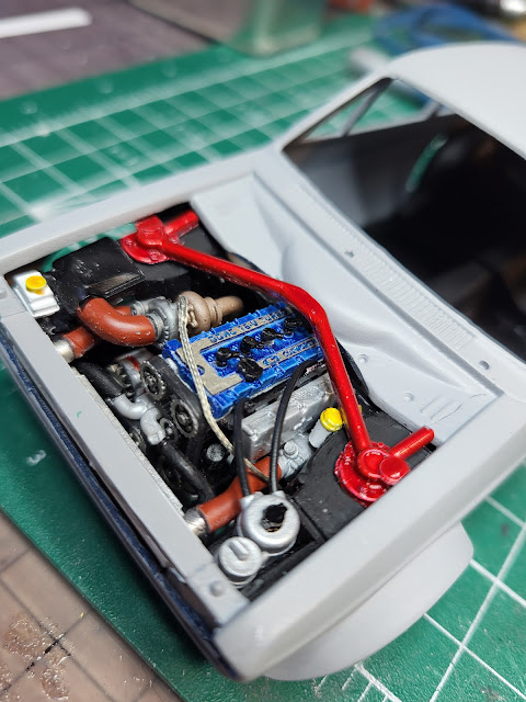
Got the engine bay complete and added the interior. Still a crappy kit. But it's getting there. Just need to choose a paint colour for the body.


Stay tuned!
Got the engine bay complete and added the interior. Still a crappy kit. But it's getting there. Just need to choose a paint colour for the body.


This 1953 Lancia D20 is a 1/24 resin kit from Profil 24. First one complete for 2024. Not one of my better builds but at some point you have to get it off the bench and into the display cabinet.

An unusual car, apparently unrelated to any Lancia road cars of the time, and a perfect topic for Profil 24. As always kits from small cottage-industry kit makers reflect the passion and world view of the founders, and you had better be prepared to accept the quirks, such as the weak hubs for the wheels. I am considering fabricating these from brass tubes in the future...

Lancia made 7 of these, of which two were prototypes. This one, apparently the last one made, was driven to first place in the 1953 Targa Florio by Umberto Maglioli. In that race it ran with a 3 litre V6. The Italian version of Wikipedia implies the D20s all had inboard front drum brakes (!!) and a de Dion tube in the rear, but this kit doesn't have the detail to confirm this.


According to the Pininfarina website, four additional D20 chassis were converted to D23 Spiders; this led to the well-known D24. It's not clear if any of the original D20s survive.
Stay tuned, you never know what's next.
So I have a Faithful Reader, who knew? Cause for celebration, I'd say. "Aurfalien" has been fighting the HRM kit of the Miller 91. Pics below, some new and some from the build, are meant to help clarify some questions around the front suspension. Comments are based on my experience as a car mechanic (although not on Millers!) Feel free to write again.

Hopefully this explanation is not too simple! I've been accused of pontificating in the past. So here goes: Front suspension on this car is unusual due to being a 1926 vintage front-wheel drive setup; very little looks like a modern FWD car. The drive part starts with the transmission which sits at the front of the engine, under the radiator. Drum brakes are inboard, up against the transmission on either side, then there are driveshafts extending out to the wheel hubs. The two driveshafts were actually modelled in the kit as a single long aluminum tube joining both sides.

The axle consists of a de Dion axle; this is the bent tube that joins the two front wheel hubs and runs in front of the transmission. This has two big brackets per side, each bracket bolted to a quarter elliptic leaf spring (painted in a bronze metallic colour) which run rearwards and are anchored in the chassis. So the tube is free to move up and down on the leaf springs, carrying the hubs with it; the axle can't move back and forth (much) due to the springs acting as trailing arms. Brake and drive torque is taken through the driveshafts growing out of the drum brakes.


The shock absorbers front and rear are friction type units, basically a round stack of clutches. In front, the round part attaches to the frame, with a long arm reaching forward to the de Dion tube. As the tube moves up and down, the stack of clutches is rotated but resists motion due to friction, thus providing some (highly non-linear) damping.

The steering linkage (see photos further down) starts with an arm on the left side of the cockpit, on a shaft coming out of the steering box under the cowl, that drops down and connects to a long rod leading to the left front hub. Another rod (apparently pushed through a hole in the bottom of the transmission, but don't quote me on that) crosses side to side and joins the left hub to the right hub, so that when the left wheel is steered, the right will follow. These rods were probably brass tube or aluminum rod that had to be cut to length.
In back, suspension is a simple beam on elliptic leaf springs.


Regular readers (if any) will know I am not afraid of spoking wire wheels at 1/12 scale. The Alfa P2 (192 spokes), Auto Union Type C (224 spokes), Ferrari 156 (288 spokes) and the Honda RC166 (72 spokes) all went together reasonably well for a lifetime total of 776 spokes so far. So perhaps I could be forgiven for thinking another 72 spokes on this Honda RC110 would be, if not necessarily a breeze, at most a moderate challenge.

The wheel consists of two photoetched rims, joined to the hubs by a pair of sacrificial strips. Spokes are cut from 0.25 mm wire provided, bent and glued to little grooves etched in the PE piece. The first row goes on OK but subsequent rows involve knocking earlier spokes off. So as you get to the last of 18, each spoke involves one step forward, three back. Bah.

Then once you've got two half-rims done, you stick them together with a plastic hub in the middle. It is sad that I have had to rely on great gobs of 5 minute epoxy to (hopefully) hold the first 36 spokes together.

Frustrated with the Ossa Monocasc and its bazillion little breakable rivets, but wanting to complete a bike, I tackled the Gunze Sangyo High Tech kit of the Honda RC 110, an unsuccessful 50 cc GP contender from 1962.


