Monday, April 21, 2025

Ferrari 250 LM: Fitting the body

Well now. Perhaps I was getting a little cocky in thinking this was all going to go together like a breeze. A little too easy, perhaps, and I was lulled into a false sense of security by my arch-nemesis Murphy who targets me unceasingly in spite of my always giving him his due and doing all the necessary bowing and scraping. But I digress.


Turns out the rear engine lid doesn't line up with the rear valance (as shown below), in spite of a test fit prior to painting (as shown above) showing that it does. So possibly something is holding the body up, although it is hard to see what that might be. I also screwed up a decal (thank goodness for indycals.com) and broke one of the excessively flimsy hinges for said rear engine lid, so it was time to step away before I accidentally wound up heaving it out the window in a fit of frustration. 

So it's sitting on the Shelf of Doom until the decals arrive, and until I can suss out what went wrong. I'll also need to redesign the silly little hinge with something involving real metal. 

Meanwhile I am considering a stress-breaker in the form of a 1/24 kit. These big kits are lovely but this has been the only thing on the bench since mid-December. Stay tuned!

Tuesday, April 15, 2025

Ferrari 250 LM: Windshield

Well, now, this was different. Model Factory Hiro's 1/12 kit of the Ferrari 250 LM comes with an actual windshield rubber gasket and a length of wire to lock it into place. It also comes with a gasket for the rear window separating the cockpit from the engine bay, but that's simpler and less in your face once done.

Starting with the rear window, the photo shows the finished product which was relatively simple: glue the rubber to the body with Micro Kristal Klear, then force in the sheet of clear styrene cut to fit. A bit fiddly but it works. 


The windshield is a whole other story because the piece is so big and has to be cut carefully from the vacuum-formed sheet, and because the wire lock adds complexity. So I thought I should document this. First up is the instruction sheet. 


All very tidy and I started with the rubber gasket as described. I used Revell Contacta Clear contact cement along the inside, squooshing it up inside the gap with the body. Tape was used to keep it all in place while the glue set.. 


Then I cut out the windscreen, and used a file to sharpen the edges so it would slide into the slot in the rubber more effectively. I also used a toothpick to lubricate the rubber slot with Dawn dish soap. A lot of struggling ensued, possibly because I had cautiously cut the window a bit big, and the rubber eventually broke lose from its glue joint. 

There are no pictures of this event. 

Take 2 involved scraping off all the Contacta Clear and underlying paint from the inside of the cabin. This was pretty easy, the stuff scrapes off nicely taking the paint with it, and getting it off the rubber wasn't too onerous either. A new fit caused the rubber to settle into the lip in the body a little deeper, due to the paint removed; then I trimmed the window a bit. It turns out that I went a little overboard on the trimming, but I still managed to get the window to sit where it belongs, held in by Micro Kristal Klear (the white line in the photo; this dries clear after an hour or two). 


You can see the gap where the Micro Kristal Klear isn't quite filling the gap at the top of the left-side A pillar. I'll build that up with successive layers of Micro Kristal Klear over the next while.


On to the wire. The kit provides a length of soft aluminum wire (0.048" diameter) and a resin jig with which to bend it. 


Note that 0.0475" at 1/12 scale is 9/16" (14.3 mm) at full scale, and seems to me to be a bit big in terms of scale. Also (and more relevant to the discussion), I couldn't see forcing a wire that big into the gap in the rubber gasket without displacing said gasket, even in the context of the instructions showing the wire only going in to a depth about half its diameter. So I substituted some lead-free soldering wire (0.031") which is glued in only at the joint between the two ends under the clamp. It all seems to be holding... perhaps 1 mm wire (0.039") could have worked too.


Once it all sets, there will be some cleanup of the glass and maybe a very gentle polish as there are a few scratches to deal with. 

Oh and if you've read this far: put the windscreen in as soon as you are happy with the paint and decals, and before you join body to chassis. The instructions tell you to put it in once the body and chassis are mated, but this way lies madness. You'll never get your fat fingers up inside the cabin above the dashboard to hold it all in place. 

Stay tuned! I'll keep you posted.

Sunday, March 16, 2025

Ferrari 250 LM: Cockpit and forward chassis mated to the rear chassis and engine

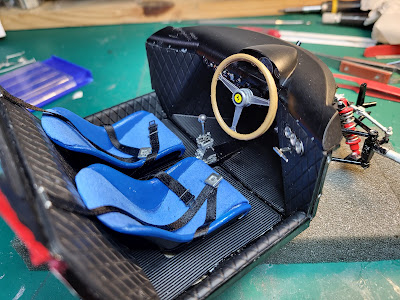
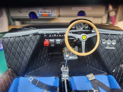
The cockpit is essentially done. One nice touch is the rubber pieces that mimic the quilted interior. 


Front suspension is done, leaving just the brakes to do. 


One of the biggest challenges with these 1/12 scale Model Factory Hiro kits is mating the cockpit to the rear chassis and engine bay so that the result is straight and flat, and the body lines up properly. 


Lots of filing, bending and test-fitting before taking the plunge and getting out the 5-minute epoxy and my larger clamps. I'm committed now! 


 Next on to the body, which appears to be fairly flimsy requiring some internal reinforcing bits to be glued in. I suspect I should use the 5-minute epoxy here as well. Stay tuned! 

Sunday, March 2, 2025

Ferrari 250 LM: Rear chassis complete

A milestone: The rear chassis components are complete, with the exception of splash shields that will go in with the body work, fuel filler caps with very fragile hinges that won't stand much handling, and that &%#$ left rear exhaust manifold which fell off again. 


Paint touchups will be undertaken as part of final assembly. I've learned not to worry too much about scrapes and scratches at this stage. On to the cockpit. 

Stay tuned!  

Wednesday, February 26, 2025

Ferrari 250 LM: Rear chassis

Next step was the rear chassis, made up of a bunch of tubes. Some are made of brass tube pre-cut to the correct length, which makes for reduced risk of the chassis being twisted or bent once complete. 


Initial fitting and gluing up major chassis parts, using the engine and transmission mounts as hard points that the chassis has to conform to. 


Fit to the bulkhead and the rear valance is also important and helps line everything up.

 
Paint is on the main components after gluing it all together. Getting the front section of piping on required about 6 hands but it all seems to be working.

 
Details of the oil and fuel filters and associated piping. This will of course be invisible once the fuel tanks are in place. 

 
Coolant is piped to the radiators through chassis tubes. 


Of course a lot of this will be hidden once the gas tanks and bodywork is all in place. Stay tuned! 


Saturday, February 8, 2025

Ferrari 250 LM: Engine complete

With the cam covers on, the internal detail is no longer visible, but I've got pictures.  


Moving on to carbs, ignition and auxiliary stuff. 


Next up is the transmission with inboard brakes. The rear subframe, made up as it is of a bunch of white metal tubes, may need to wait until I have the cockpit f;oor and firewall set up so as to ensure alignment. Stay tuned! 

Sunday, January 5, 2025

Ferrari 250 LM: Engine internals

The engine in the 250 LM comeswith loads of internal components which could very well be left out, because no one would ever notice. However after some deliberation I decided to assemble as spelled out, and document the heck out of it. 

The pistons are cast in one piece, meaning the crank has to be built up. This leads implies lots and lots of bits, including wrist pins made from brass wire. 


Once assembled, the crank, rods and pistons flap around a bit. Also part of the build-up is 5 of the 7 main bearing blocks which are sadly not split. 


The engine block being made in two halves, it is impossible to insert the assembled crankshaft with 12 rods and pistons into the assembled block all in one go. Rather it is necessary to insert 6 pistons into one half of the block, carefully gluing the main bearing blocks to the block but not the crank, then carefully slip the other half block over the remaining 6 pistons and glue it all in. 


Of course I tried to turn the crank to see how well I assembled the whole thing, but it went a quarter turn before jamming, and applying a bit of torque caused the crank to break. So the last journal, carrying the rods for the last two cylinders, is now independent of the forward five journals carrying the remaining ten rods and pistons. You have now been warned: don't ask me to assemble your crankshaft if you expect it to turn.

The lower crankcase and oil pan are now in place and the crankshaft is forever sealed in there where no one will ever see it again. 

Next the valves and valve springs (made of white metal, sadly) went into the cylinder heads, and assembled heads were attached to the block with the appropriate gaskets.


The next step involved adding the camshaft drive gears in their front cover (also now hidden forever), the flywheel housing and the intake manifolds before painting the whole thing with a mix of 1/3 dark aluminum (ZP-M1004) and 2/3 light aluminum (ZP-M1001) from Zero Paints.  


Next were the camshafts, one per bank, and the rockers, each on its own rocker shaft mounted between two camshaft bearing blocks. For some unfathomable reason, the cam bearing blocks are not fitted to the head with a precast dowel and socket approach, but with 48 bits of 0.5 mm diameter wire, each 5 mm long. 


Finally the cylinder head internals were covered with Tamiya's brown panel line accent colour to mimic oil residues; I wiped the worst off the rollers on the rocker ends to mimic the machined finish here. 


This will never be seen again once the cam covers are on. However, it is now documented that I actually did it.

And that's it for now.