Monday, August 26, 2019

Ferrari 156 Sharknose: Chassis II (getting it all straight)

Got the front chassis bits to line up with the cockpit chassis bits. All this is a real challenge. The steps were the following:


1) Get the cockpit assembled and straight. This was helped by the fact it is made up of couple of substantial flat pieces (floor pan and seat back), which nonetheless were not quite straight. The forward bulkhead helped locate the upper rails and the intermediate vertical struts joining the upper rails to the floor. Tack in place with CA glue. 


Mold separation lines are visible on the upper horizontal rail of the chassis. These will have to come off.


Slight bending of everything is critical to get it all to line up. The seat back structure, while substantial, was slightly warped and needed to be straightened.


2) get the engine structure to line up with the cockpit, assuming the cockpit is straight ... you have to start somewhere. The only bits not tacked in place are the rearmost vertical struts which are free to rotate in their sockets; the lower A-arms will need to be used as a template to line them up. The entire upper set of tubes can only be finalised once the engine is in place, adding to the logistical challenges.


The rear chassis bits have been polished and are ready for primer.


Getting upper and lower horizontal pieces to line up wit the motor and transmission, 6 vertical struts and the cockpit was a real exercise in the fiddles.


The next view shows it all together, missing just the rearmost vertical strut that locates the rearmost lower A-arm mounting point. The A-arm will serve as a template to get it straight before final gluing.


3) Get the forward structure to line up with the cockpit. As with the rear structure supporting the engine, there are about 6 pinned joints that all have to line up.


As with other structures, this consisted of upper and lower components and at least two vertical struts per side, all having to be held in place while test fitting and, eventually, dribbling in the CA glue.


4) Once all the other bits go in, it will all get strengthened with a bunch of 1.4 mm screws.
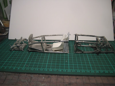


Only two pins broke off during all the manipulation, and both have been drilled out and replaced with 1/32" brass rod which is equally flexible but far harder to snap off.


Next: I am debating whether to just forge ahead with scraping off mold lines, polishing, drilling and paint, or to drop it all in an acetone bath to dissolve the CA glue and start all over with much stronger solder or 5-minute epoxy.


This beast will weigh close to a kg when done and I want the chassis to hold together. Solder is recommended by several Netizens of the Interweb, in particular on the MFH build group on Facebook who presumably know what they are talking about, but is scary. I have nightmares of the whole thing turning into a blob of molten metal on my bench...


Baby BRM and mid-sized Honda are dwarfed by this beast. Stay tuned!

Friday, August 23, 2019

Ferrari 156 Sharknose: Chassis I

With the engine close to complete, I thought I'd see if I could get all the chassis bits to line up.


If I thought these 1/12 scale white metal chassis tubes would be stiffer than the 1/24 equivalents, I was wrong. Lots of minor bending and fiddling was needed to get pins to line up with sockets, without snapping pins off. Only one pin, a ridiculous 0.5mm item, has been lost. Most are 1.4 mm, but still flexible.


Getting the engine out of the chassis looks to be a major challenge, unless there are bolted-in chassis bits, which does not appear to be the case ... so what happened when Phil threw a rod? Right, Phil didn't throw rods. The gearbox comes off the back OK and perhaps the engine can be lifted out once one of the cylinder heads has been removed, or at least the exhaust cam covers. The 120 degree V6 certainly takes up a lot of width.


The frame is poorly triangulated. It may have been a beautiful car but the Lotus and Cooper folks, with their fancy new monocoques, were just waiting for a decent engine to beat the Ferraris.


It's all held together with crazy glue at this point. I'll take off the upper tubes around the engine, then toss the chassis in the acetone bath to clean it all up and strip out the glue. Then polishing and paint, and another test fit as I will no doubt bend a few bits here and there. Final assembly will be with 5-minute epoxy, unless I get brave enough to learn how to solder again. I am told I need 70 degree solder, and obviously some form of mini-torch. To be continued...


Stay tuned!

Tuesday, August 13, 2019

Ferrari 156 Sharknose: Engine IV

Progress on the 1/12 Sharknose has been slow, due to life intruding. I thought the water hose clamps supplied were way too big so I dug these 1/24 units out of the parts box. I am pleased with the success of the throttle linkage, just out of focus behind the water pipe and reservoir; I am hoping to be able to replicate this at 1/24 on future builds. 


The wash looks pretty good from a distance but obviously gets rough with the unforgiving camera eye. 


Also the wash looks a little heavy; perhaps this is after a race.


Lots of detail in this kit. The fuel fittings are neat; the brass paint may not be original (the kit says aluminum) but they sure do stand out.  


Next is the gearbox and assorted bits before the rear sub frame needs to wrap around the drivetrain. My experience with past MFH sub-frames made of flexible white metal is that getting this straight will be absolutely critical to getting the car to sit square on its four wheels. Test fitting it to the tube frame around the cockpit will be part of the solution to this challenge. I wonder if I should also be building up the front suspension structure as well so that all three units can be test-fitted together ... One approach will be to glue it all together with CA glue, make sure it's straight, then into the acetone bath to dissolve the CA and start over with paint. 

Stay tuned!

Wednesday, August 7, 2019

Ferrari 156 Sharknose: Engine III

I saw some photos of a superb build of this kit on a Facebook page devoted to Model Factory Hiro kits. In particular the builder made use of washes to make the aluminum bits look like aluminum that has gotten oily and hot; the metal in these situations weathers and takes on a dull, slightly oily hue that, in my experience as a mechanic, doesn't come off when you wash the part in Varsol or other heavy solvents.


So on to a new frontier: Tamiya Panel Line accent colours, which are very diluted enamel paints with a fine powder in suspension. It flows on with a wet brush, and the powder heads for sharp edges and grooves through capillary action. Once dry it becomes a very realistic weathered aluminum finish. Here I've done the right side cam covers and into the valley in the cylinder head between them. Note that the base finish is Tamiya TS-17 Gloss Aluminum.


I've also got a bottle of gray which I may use on the carbs which presumably are die-cast instead of poured, so different reaction to heat (and less heat to start with. I am also playing around with a 50:50 mix. 


It's still blotchy and another coat will be needed; hopefully I'll manage this without overdoing it. But so far I like it. It's a little late to be stripping paint ...


Saturday, August 3, 2019

Ferrari 156 Sharknose: Engine II

The engine is essentially complete, including wiring, plumbing and throttle linkages.


For the plug wiring, I used 0.020" (0.5 mm) wire from the stash instead of the 0.024" (0.6 mm) wire supplied.


The tubing is 1.2 mm OD but the little brass rod supplied as dowel is quite loose inside it at 0.4 mm. A heavier gauge of wire makes sense and I will use material from the stash from here on where possible. I have some 0.032" (1/32", 0.8 mm) brass rod that is a bit snug inside the tube; this would be a challenge to install but won't risk falling off after. The main issue will be whether there is enough metal to drill out a big enough hole for the bigger rod. 


The throttle linkage was entertaining given I had put on the water pipes too soon, and I had to work around them. Just missing the water filler cap, and the very fiddly hose clamps.


I am worried the carbs lean into the V a little too much and might be difficult to line up with the body panels later. There is not much to be done about it now, because the white metal inlet manifolds are glued into the resin block with CA glue, so acetone is definitely contra-indicated -- don't want to melt the resin! To be continued.


So 1/12 is not really much more detailed than 1/24, at least so far. I have struggled about as much with smaller kits for about the same level of realism. Perhaps the biggest difference is I can actually see stuff that is getting glue, this reducing glue blobs. To be continued.