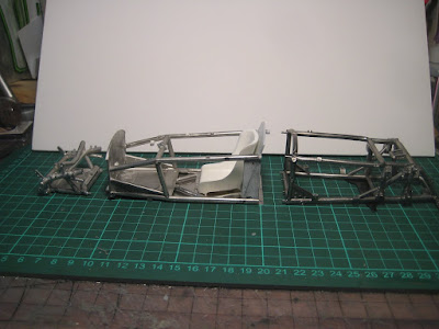
1) Get the cockpit assembled and straight. This was helped by the fact it is made up of couple of substantial flat pieces (floor pan and seat back), which nonetheless were not quite straight. The forward bulkhead helped locate the upper rails and the intermediate vertical struts joining the upper rails to the floor. Tack in place with CA glue.

Mold separation lines are visible on the upper horizontal rail of the chassis. These will have to come off.

Slight bending of everything is critical to get it all to line up. The seat back structure, while substantial, was slightly warped and needed to be straightened.

2) get the engine structure to line up with the cockpit, assuming the cockpit is straight ... you have to start somewhere. The only bits not tacked in place are the rearmost vertical struts which are free to rotate in their sockets; the lower A-arms will need to be used as a template to line them up. The entire upper set of tubes can only be finalised once the engine is in place, adding to the logistical challenges.

The rear chassis bits have been polished and are ready for primer.

Getting upper and lower horizontal pieces to line up wit the motor and transmission, 6 vertical struts and the cockpit was a real exercise in the fiddles.

The next view shows it all together, missing just the rearmost vertical strut that locates the rearmost lower A-arm mounting point. The A-arm will serve as a template to get it straight before final gluing.

3) Get the forward structure to line up with the cockpit. As with the rear structure supporting the engine, there are about 6 pinned joints that all have to line up.

As with other structures, this consisted of upper and lower components and at least two vertical struts per side, all having to be held in place while test fitting and, eventually, dribbling in the CA glue.

4) Once all the other bits go in, it will all get strengthened with a bunch of 1.4 mm screws.

Only two pins broke off during all the manipulation, and both have been drilled out and replaced with 1/32" brass rod which is equally flexible but far harder to snap off.


Next: I am debating whether to just forge ahead with scraping off mold lines, polishing, drilling and paint, or to drop it all in an acetone bath to dissolve the CA glue and start all over with much stronger solder or 5-minute epoxy.

This beast will weigh close to a kg when done and I want the chassis to hold together. Solder is recommended by several Netizens of the Interweb, in particular on the MFH build group on Facebook who presumably know what they are talking about, but is scary. I have nightmares of the whole thing turning into a blob of molten metal on my bench...

Baby BRM and mid-sized Honda are dwarfed by this beast. Stay tuned!
No comments:
Post a Comment