Friday, July 26, 2019

Ferrari 156 Sharknose: What have I done?

So in a fit of weakness, I went out and splurged on one of Model Factory Hiro's 1/12 kits, specifically the 1961 Ferrari 156, known as the Sharknose for its distinctive radiator fairing, as driven by Phil Hill to the championship that year.


One reason for doing this is that it appears MFH has lost their license from Ferrari to sell kits, so once existing stock is gone, that's it. And the vultures are selling this stuff for a fortune on eBay.


Gotta give MFH credit: ordered from Japan on July 21, delivered in Eastern Canada on July 26. So on to the box, classy as always:


The new MFH kits feature more resin and less white metal than past kits. This kit has a resin engine, and I am sure the result is a significantly reduced weight overall. (Some online posts describe the 917K at this scale wanting to bend in half, due to the weight of the big flat 12 when cast in white metal). That being said, the kit clocks in at 1100 grams, of which the seven bags of white metal bits represent 800 grams.


The wheels in particular look to be gorgeous, but I have to do the lacing up myself; this occupies a full two pages in the instruction manual.


There are only three photo-etched sheets, and a few mechanical bits like springs and screws in a separate bag. There is a piece of blue velours on sticky backing for the seat upholstery, and I hope that this will be relatively easy to keep clean once built.


So on to the baggies of white metal bits.


The first baggie, the biggest one, has a range of chassis bits. Lotus had monocoques by 1961, but Ferrari was sticking with the familiar tube frame. Fortunately these are nice and sturdy, unlike the 1:24 tube frames from MFH that I have assembled.


Sadly, the jig for lacing up the wheels is bent. I am told that MFH service is wonderful so I may try to get a new one.


Baggies 2 and 3 contain different bits related to bodywork and interior, as well as cam covers and exhaust pipes. After the spaghetti maze of the 908 and 917 exhaust systems, the simple V6 pipes are a joy.


More bent sheet but that is OK.


Baggie 4 is more engine bits along with brakes and suspension bits. There is also a large selection of 'bolts', some of which may get replaced by actual #00-80 bolts.


Baggie 5 has chassis struts, A-arms and an assortment of more or less bent tubes.


Baggie 6 has a mix of stuff, much of it unidentifiable at this stage. The battery is remarkable, being a 12V and a 6V battery wired up in series for 18V. I wonder what needed 18V in a 1961 GP car? The early version of the car had an additional 6V battery mounted immediately behind the dash. A fuel pump and a couple of magnetos ought to do it in my view, especially when dealing with the electrical needs of a carburetted 1.5 litre V6 making 190 hp. Then it occurred to me to have a good look through the manual: it appears there is no alternator to keep it all recharged. So the car gets a fresh battery on race day and off we go!


Finally Baggie 7, which I won't open just yet, is a load of little pins, rivets and other assorted connecting bits.


The little 120 degree V6 is made up of about 6 resin parts, plus the transmission. It's all on a sprue and looks almost like styrene. The 156 engine (meaning 1.5 litre, 6 cylinder) in previous years was a 65 degree unit; the new flatter engine for 1961 was balanced (which a 65 degree unit will never be) and could thus rev higher, as well as having a lower centre of gravity. Partly as a result of the new motor, and partly due to the driving of Phil Hill, the new car was unbeatable in 1961. The aluminum rims are just lovely and getting them straight will be a major operation, even with a straight jig.


All in all a classic shape. The kit does not, yet, appear to have much more detail than a 1:24 kit, so hopefully easier ... but the quality of final paint on the body will make or break it. Do I dare use Tamiya rattle cans? Stay tuned!

Monday, July 22, 2019

Lotus Elan S3: Final assembly Part I

Having put aside the Elan to build the MAZ, the MAZ is now on hold while putty sets. So back to the Elan.

The rubber gaskets around windshield and rear window were the deal breakers that led me to put it aside last time. I managed a so-so job, using a two-step approach:


First, I held the rubber in place in the corners using plastic clamps. Then I peeled back the gasket and applied crazy glue (yes, I am brave) to the groove along the top of the window and along the base of the window. Then I gently pressed the rubber into place with a #11 knife. (I use the medium speed, 5-15 second glue).


Second, I removed the clamps and pushed a little glue up inside the corners to keep it all from lifting.


Overall I was moderately successful; there's glue on the windows and a bit of paint damage to fix.


Finally I'll have a crack at the 0.3 mm aluminum rod used to model the chrome strip that wedges the gasket into place in real life, but I may decide to skip it. 0.3 mm is only 0.012" so quite flexible.

MAZ 537: Cab (again) and drivetrain (still)

The resin cab continues to be a problem. The first batch of primer covered the cab completely, but didn't stick; this second attempt, after stripping, cleaning in Purple Power and respraying, showed two spots where paint stuck the first time, but now wants to run from some sort of chemical contaminant. Argh. So it's back in the isopropyl bath (and beware: 24 h in isopropyl can make the resin soften up).


Meanwhile I have scratch built catwalks, exhaust system, a support for one of the two gas tanks in the kit, and a big roof-mounted scoop to feed the turbo. Sadly the scoop faces a bunch of hot air exhaust vents on the roof of the engine compartment rather than cool fresh air, but so be it.


I just need to route the wastegate outlet to the main exhaust pipe. The triple lake pipe came from Italeri's truck accessory kit. The main exhaust is painted Testor's Flat Rust which is a pretty poor imitation, frankly. I may need to redo this.


It's getting crowded back there, and it would be nice to have a duct leading down into the turbo inlet which otherwise is sucking from around the gas tank.


Just missing the breather on the forward valve cover, and the connection from the wastegate to the exhaust.


I saw somewhere on the Interweb that fuel consumption for this beast is 140 litres per 100 km, which is just about 14 times what my trusty Volvo, Thor, gets me. So having only one tank, and at a smaller scale at that, may be limiting, but I want to make sure there is nothing back of the 2nd steering axle to interfere with payload, so this may be it.


Here is the current state of the extended engine cover, fabricated using bits from the 1:35 winch housing and random bits left over from the 1:35 light tank which I cannibalised for my SSP (Super Snow Plough).


So the chassis is looking good, at least. I'll add a few other bits like a battery box from the Freightliner kit. Hopefully there will be a painted cab at some point.


Two steps forward, one back, which is better than two back, one forward. Just getting some additional putty on the roof before beginning final assembly. Stay tuned!

Sunday, July 7, 2019

MAZ 537: Cab and drivetrain

Some random progress over the last little while.

The cab now sports a three-tone paint job, marred by a couple of spots where the primer and all layers of paint on top of it have peeled off with the tape, in spite of leaving it all for over a week to settle.


I have had this problem with resin before and I'm not sure what is not working; I am sure that the Duplicolor primer sealer is a common item; maybe I need to reconsider this as my go-to base, or review my resin cleanup approaches. The Interweb insists that a tire bleaching chemical called Blechly (yes, really) is the ticket; one correspondent said Easy-Off would do the trick of getting rid of the mould release agents which are probably at the root of this.


With the cab painted, and while waiting to decide about stripping or patching the paint, I glued in the engine and the two deck plates either side of it.


With these fixed in place, I scratch built the piping to the intercooler. Bits of exhaust from the Cummins have been pinned together with 1/32" rod.


Deck plates came from the Italeri truck accessories kit.


With paint these are looking good. I have taken hose clamps from the spare PE drawer.


The cab is probably heading for the stripper, in part because I am not that happy with the paint colours.


Regardless of the paint scheme, the truck is really coming together, and the cab can be glued in at the last moment. Next will be the coolant radiator on the other side of the engine. The exhaust pipe will be finalised at a later date; I like the view of the compressor so I am probably going to skip the air filter. 


Stay tuned!

Thursday, June 27, 2019

MAZ 537: Chassis, interior and body progress

There has been a lot of progress in the last few days, starting with chassis upgrades.


The scratch-built steering linkage (brass rod in the photo above) leads to the White Freightliner steering box attached to the MAZ chassis under the floorboard. The linkage is correct, except that it might foul the wheels as they steer. The mechanism as provided in the kit disappears into the engine compartment, where it is out of the way of rocks or land mines, but where it interferes with the Cummins. As this is meant to be a civilian vehicle, there is no need to beware of land mines.


On the other side of the chassis, a range of brass pipes replace styrene oil pipes that proved to be a little too flexible when faced with my clumsy big mitts. One appears to be feeding oil to the Cummins motor mount but we'll let that go; the MAZ kit had no engine and these parts just sort of disappeared into the engine compartment.

The interior will be a squeeze for my buddy Fred. Fred and his lady friend Doris came into the house with the Lincoln Futura kit and will be part of the road testing and cockpit evaluation team going forward, once I do something about their pasty-white complexions.


Colours mimic the proposed body paint. The dashboard will go into the body once it is painted, then the floorboards, and finally the steering wheel will need to be inserted through the windshield and dropped on to the column.


Moving on to the body: Cutting is complete, and there is enough left over to build mudguards over the second axle.


Initial putty application is shown here. Several rounds of putty, primer, sand, repeat were required.


Dupli-Color primer-sealer remains my favourite to seal resin and identify high and low spots. This primer does a great job of filling small holes and scratches. I find it to be better than the darker sandable primer which includes a polymer of some kind, and which isn't well suited to Tamiya paints or primer. (I know there are dissenting opinions out there and I'd be glad to hear them.)


Final application of Tamiya primer over the Dupli-Color is shown here. I feel that the Tamiya primer, which works very well on styrene, doesn't do at all well on resin, no matter how clean it is, because the Tamiya gets sucked into pits and pores and doesn't ever stick to the surface. The primer-sealer provides a surface the Tamiya primer can stick to.

Next will be the final paint, probably a 3-tone arrangement. Stay tuned!

Saturday, June 22, 2019

MAZ 537: Techniques for preparing a chop or section

One of my favourite sports is cutting up perfectly good car bodies. Lately I've gotten a little more tactical in the planning. I take a series of photos and then put them all together to decide where cutlines will go. Here are three such photos for the MAZ/White, starting with the forward chassis and engine.


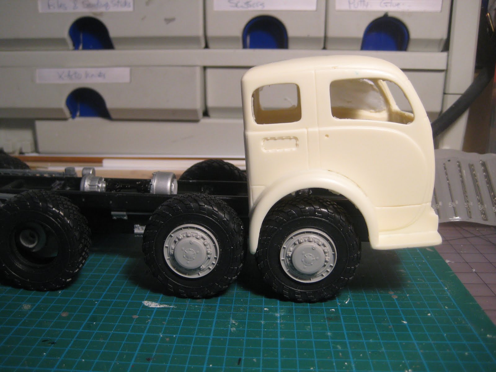
Next the Jimmy Flintstone cab is perched on the chassis, lined up with the forward axle. It's tilted because of interference with the chassis at the front.


Finally here is what it would look like OOB.


By putting my camera on a mini tripod, and not moving either the camera or the chassis between shots, I know the photos can all be overlaid to compare without worrying about scale or perspective changing.

There are a range of different software approaches to playing 'cut and paste' on the computer; I use Power Point to move pictures around, trim and rotate them, and play with transparency. Here's a screenshot. Pictures were rotated slightly to line up the wheels with a horizontal red line. Other red lines show where things will line up, left to right or top to bottom, and where to cut. For example, the vertical red line on the far right shows the forward extent of the engine (bottom photo), relative to the White cab (top photo). The scale marker is obtained from the distance between the two axles, which is just about 50 mm on the model; when printed on 8 1/2 X 11 paper, the distance is actually 27 mm. 


The next picture, an enlargement of the one in the upper left corner above, shows the White cab, cut in two and split to bridge both wheels, with the MAZ engine cover inserted. The cab is also level and lower on the chassis than in the earlier pictures, in an effort to get a good feel for the stance.


It looks like it will all just about fit, so out comes the saw. First was to cut a slot in the bumper and grille to allow the MAZ chassis to poke through, and let the cab settle lower over the axles. Then I took 6 mm off the fender lips to better fit the wheels, and also because the White was 12 mm wider across the fenders than the MAZ width across the wheels.


Then I took off the roof, because I intend to chop it, and because it will be easier to reach through the open roof and put in a floor that supports the cab at the right height. I started off with a very fine 54 tpi saw blade but this is not really necessary with this level of resin; most of the cuts were done with a 40 tpi blade. Some straight cuts were started with the back of a #11 blade, then the excess snapped off.


After getting the floor, which is cut from 0.060" styrene, well underway, I cut off the back of the cab and glued it to a shortened forward cab section. One interesting learning here is that it is a lot easier to cut up a thick resin casting than a delicate thinwall styrene molding, which would likely tend to flap around and break with this extreme level of hacking. The cab, consisting of doors and forward grille, is pretty sturdy and inflexible which makes measuring and marking a lot easier.


The engine just clears the new, shorter cab. Radiator and intercooler will sit facing the sides of the engine cover as in the MAZ chassis. I doubt this device will ever get going fast enough to generate any reasonable airflow through a front-mounted radiator so this should be OK! Lots of fans will be needed. Maybe I'll hang an oil cooler under the floor in the front. 


The remaining piece of the White cab will serve to build up the rear fenders. I may have enough leftover material to fill the gap in the engine cover above the turbo, or I may need to scratch build that; to be verified.


Lots of fitting, filing and gluing to go; there will be a catwalk joining the two fender halves, and the roof needs to be shortened to fit. But the general shape of the cab and engine cover is getting there, and so far it all seems to fit. I am hoping to do all this without modifying any of the parts from the MAZ kit, so that it could, theoretically, go back to an OOB build; we'll see how far I can get on that score. Stay tuned!

Thursday, June 20, 2019

MAZ 537: Drivetrain complete, mostly

I am making progress at a torrid pace, but this won't last -- social events are upcoming and I'll be busy. I may even have to do some work.


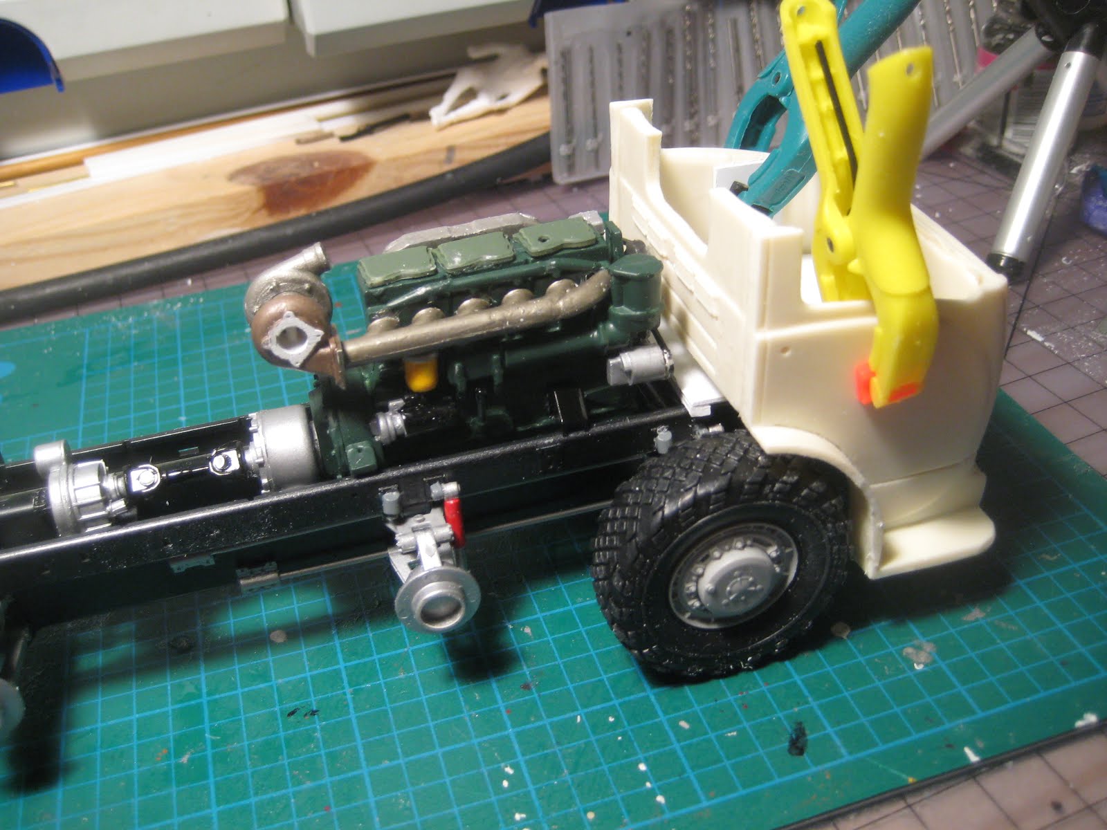
The engine now has a scratch-built transfer case to join the clutch to the transmission; in the real truck the transmission is substantially bigger and the engine is moved forwards quite a ways, but that would cut into the larger crew cabin, so we'll pretend it's OK. The oil pan had to be put in backwards so the deep end of the sump would clear a cross-member.


The turbo, which is nice and big, came from Ron Olsen at Shapeways, and is 3D printed. It's a very nice piece that also comes with a wastegate (still to be installed). The exhaust manifold was fabricated using bits from Italeri's truck accessory pack. The exhaust will likely be a short, fat pipe.


The inlet side of things still needs an intercooler, which will face the side of the engine compartment as in the real truck. (The engine radiator will also face the side but on the right side of the vehicle.) Brackets at the right distance will dictate the location and thus piping.


Stay tuned!