Thursday, June 27, 2019

MAZ 537: Chassis, interior and body progress

There has been a lot of progress in the last few days, starting with chassis upgrades.


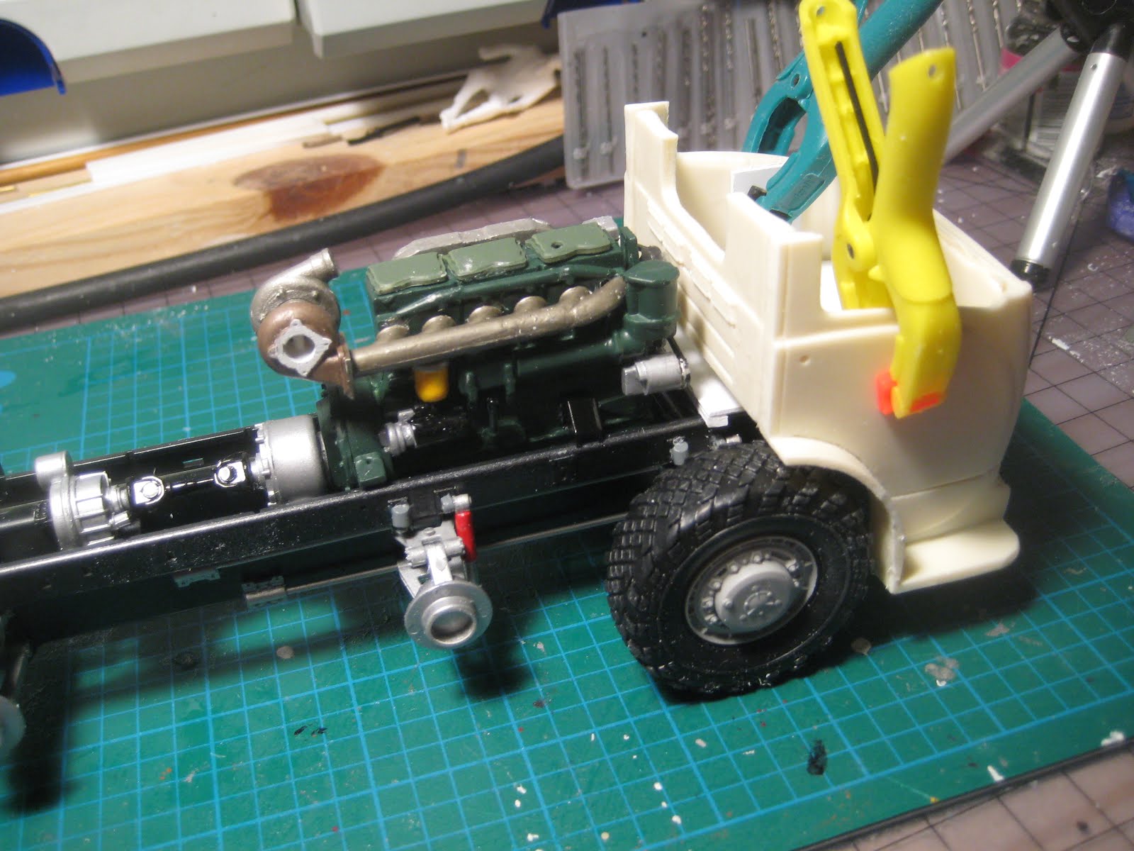
The scratch-built steering linkage (brass rod in the photo above) leads to the White Freightliner steering box attached to the MAZ chassis under the floorboard. The linkage is correct, except that it might foul the wheels as they steer. The mechanism as provided in the kit disappears into the engine compartment, where it is out of the way of rocks or land mines, but where it interferes with the Cummins. As this is meant to be a civilian vehicle, there is no need to beware of land mines.


On the other side of the chassis, a range of brass pipes replace styrene oil pipes that proved to be a little too flexible when faced with my clumsy big mitts. One appears to be feeding oil to the Cummins motor mount but we'll let that go; the MAZ kit had no engine and these parts just sort of disappeared into the engine compartment.

The interior will be a squeeze for my buddy Fred. Fred and his lady friend Doris came into the house with the Lincoln Futura kit and will be part of the road testing and cockpit evaluation team going forward, once I do something about their pasty-white complexions.


Colours mimic the proposed body paint. The dashboard will go into the body once it is painted, then the floorboards, and finally the steering wheel will need to be inserted through the windshield and dropped on to the column.


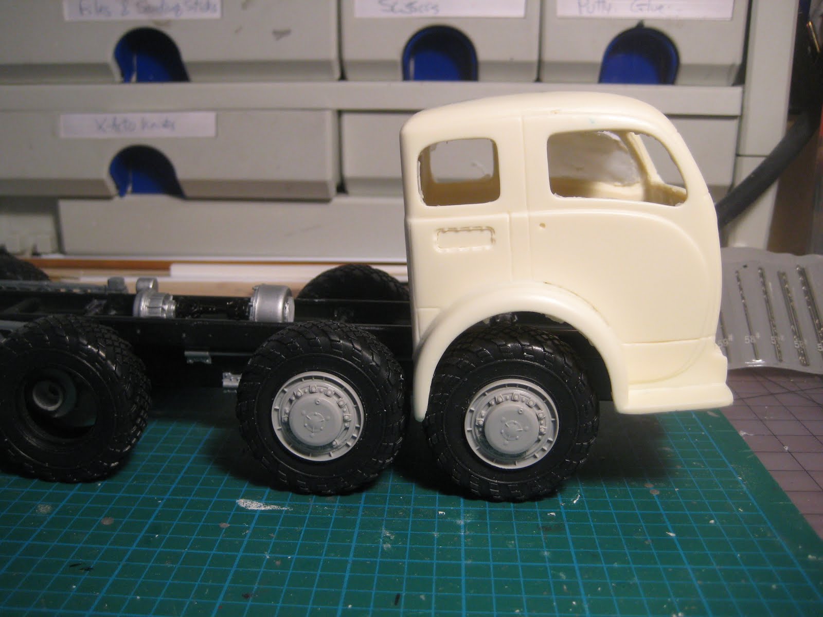
Moving on to the body: Cutting is complete, and there is enough left over to build mudguards over the second axle.


Initial putty application is shown here. Several rounds of putty, primer, sand, repeat were required.


Dupli-Color primer-sealer remains my favourite to seal resin and identify high and low spots. This primer does a great job of filling small holes and scratches. I find it to be better than the darker sandable primer which includes a polymer of some kind, and which isn't well suited to Tamiya paints or primer. (I know there are dissenting opinions out there and I'd be glad to hear them.)


Final application of Tamiya primer over the Dupli-Color is shown here. I feel that the Tamiya primer, which works very well on styrene, doesn't do at all well on resin, no matter how clean it is, because the Tamiya gets sucked into pits and pores and doesn't ever stick to the surface. The primer-sealer provides a surface the Tamiya primer can stick to.

Next will be the final paint, probably a 3-tone arrangement. Stay tuned!

Saturday, June 22, 2019

MAZ 537: Techniques for preparing a chop or section

One of my favourite sports is cutting up perfectly good car bodies. Lately I've gotten a little more tactical in the planning. I take a series of photos and then put them all together to decide where cutlines will go. Here are three such photos for the MAZ/White, starting with the forward chassis and engine.


Next the Jimmy Flintstone cab is perched on the chassis, lined up with the forward axle. It's tilted because of interference with the chassis at the front.


Finally here is what it would look like OOB.


By putting my camera on a mini tripod, and not moving either the camera or the chassis between shots, I know the photos can all be overlaid to compare without worrying about scale or perspective changing.

There are a range of different software approaches to playing 'cut and paste' on the computer; I use Power Point to move pictures around, trim and rotate them, and play with transparency. Here's a screenshot. Pictures were rotated slightly to line up the wheels with a horizontal red line. Other red lines show where things will line up, left to right or top to bottom, and where to cut. For example, the vertical red line on the far right shows the forward extent of the engine (bottom photo), relative to the White cab (top photo). The scale marker is obtained from the distance between the two axles, which is just about 50 mm on the model; when printed on 8 1/2 X 11 paper, the distance is actually 27 mm. 


The next picture, an enlargement of the one in the upper left corner above, shows the White cab, cut in two and split to bridge both wheels, with the MAZ engine cover inserted. The cab is also level and lower on the chassis than in the earlier pictures, in an effort to get a good feel for the stance.


It looks like it will all just about fit, so out comes the saw. First was to cut a slot in the bumper and grille to allow the MAZ chassis to poke through, and let the cab settle lower over the axles. Then I took 6 mm off the fender lips to better fit the wheels, and also because the White was 12 mm wider across the fenders than the MAZ width across the wheels.


Then I took off the roof, because I intend to chop it, and because it will be easier to reach through the open roof and put in a floor that supports the cab at the right height. I started off with a very fine 54 tpi saw blade but this is not really necessary with this level of resin; most of the cuts were done with a 40 tpi blade. Some straight cuts were started with the back of a #11 blade, then the excess snapped off.


After getting the floor, which is cut from 0.060" styrene, well underway, I cut off the back of the cab and glued it to a shortened forward cab section. One interesting learning here is that it is a lot easier to cut up a thick resin casting than a delicate thinwall styrene molding, which would likely tend to flap around and break with this extreme level of hacking. The cab, consisting of doors and forward grille, is pretty sturdy and inflexible which makes measuring and marking a lot easier.


The engine just clears the new, shorter cab. Radiator and intercooler will sit facing the sides of the engine cover as in the MAZ chassis. I doubt this device will ever get going fast enough to generate any reasonable airflow through a front-mounted radiator so this should be OK! Lots of fans will be needed. Maybe I'll hang an oil cooler under the floor in the front. 


The remaining piece of the White cab will serve to build up the rear fenders. I may have enough leftover material to fill the gap in the engine cover above the turbo, or I may need to scratch build that; to be verified.


Lots of fitting, filing and gluing to go; there will be a catwalk joining the two fender halves, and the roof needs to be shortened to fit. But the general shape of the cab and engine cover is getting there, and so far it all seems to fit. I am hoping to do all this without modifying any of the parts from the MAZ kit, so that it could, theoretically, go back to an OOB build; we'll see how far I can get on that score. Stay tuned!

Thursday, June 20, 2019

MAZ 537: Drivetrain complete, mostly

I am making progress at a torrid pace, but this won't last -- social events are upcoming and I'll be busy. I may even have to do some work.


The engine now has a scratch-built transfer case to join the clutch to the transmission; in the real truck the transmission is substantially bigger and the engine is moved forwards quite a ways, but that would cut into the larger crew cabin, so we'll pretend it's OK. The oil pan had to be put in backwards so the deep end of the sump would clear a cross-member.


The turbo, which is nice and big, came from Ron Olsen at Shapeways, and is 3D printed. It's a very nice piece that also comes with a wastegate (still to be installed). The exhaust manifold was fabricated using bits from Italeri's truck accessory pack. The exhaust will likely be a short, fat pipe.


The inlet side of things still needs an intercooler, which will face the side of the engine compartment as in the real truck. (The engine radiator will also face the side but on the right side of the vehicle.) Brackets at the right distance will dictate the location and thus piping.


Stay tuned!

Wednesday, June 19, 2019

MAZ 537: Rolling chassis complete

I made some progress on the MAZ 537, completing the chassis and installing all the assorted differentials and suspension bits. The chassis can now take wheels to test for stance.


Judging by online photos, the kit drivetrain is not entirely accurate, but I'll let it go. As it is, there are 4 final drive units, each presumably with a differential, and a fifth differential splitting between front and rear pairs.


The suspension consists of 8 independently sprung wheels, so there are 16 A-arms, 8 hubs and 8 halfshafts, not to mention 5 additional driveshafts joining it all to the motor. (The actual vehicle would have had seven driveshafts apart from the halfshafts, according to one Interweb source.)


The engine in the picture is a spare Cummins NHC-250 from AMT's White Freightliner kit. This 14 litre inline 6 makes a measly 240 hp, but a sturdy 685 lbf-ft of torque. This is a bit down on the WWII tank engine in the MAZ (the 39 litre Karkhiv V2 is a V12 making 525 hp and 1591 lbf-ft), a gap which I propose to rectify by the addition of a turbocharger or two. Of course, putting a 1/25 engine of 14 litre displacement in a 1/35 chassis is the equivalent of a 1/35 motor of 38.4 litres, so in actual fact it's all fine, but hey, a turbo never hurt anyone. (See math below).


Next will be deciding what to cut to make the White cab and Cummins engine fit. So far I have built up the MAZ completely stock. As a result, the option remains to buy a resin motor for it and continue with a stock 1/35 build. The picture shows the motor in the chassis, which is resting of 4 of its 8 wheels, with both MAZ (1/35) and White (1/25) bodies. The tires are humongous, filling the White fender wells even though the scale is way off. I foolishly didn't make a note of the tire sizes on the MAN in Iceland, but they were easily 4 to 5 feet in diameter.


Stay tuned!

Appendix A: for the math nerds.

Displacement D is number of cylinders, N, times cylinder volume V. In turn V is piston area A times stroke S. Finally piston area is πb2/4, where b is bore. Assuming bore and stroke are both equal to d, we have D = 0.25πNd3.

So an engine at 1/35 scale would have displacement D = 0.25πN(d/35)3. For one at 1/25, D = 0.25πN(d/25)3

So the ratio of the two scale engines, assuming the same 1/1 dimensions and number of cylinders, wold be (25/35)3, or 0.364. Put another way, a 1/35 model of an engine of 10 litres displacement, put into a 1/25 kit, is equivalent to a motor of only 3.64 litres; conversely a 1/25 model of that same 10 litre engine, dropped into a 1/35 chassis, is the equivalent of a 27.4 litre motor.

Tuesday, June 18, 2019

MAZ 537: And now for something completely different...

A number of years ago, I had the opportunity to ride in a converted NATO missile launcher in Iceland. The truck had been converted to a bus, with seats for about 40, and was intended to crawl up to a glacier research station. Great fun, and I immediately wanted to build a kit of one.


The ultimate off-road vehicle -- the big MAN Diesel makes over 400 horsepower, according to the tour guides, but torque is off the charts. One neat feature is the ability to deflate or inflate tire pressures on the fly.


 This 8X8 chassis is also used for mobile cranes, and Revell has a kit in 1/24 of the Simba airport fire truck which is both expensive and hard to come by.


So there aren't many options at 1/24, but lots of similar vehicles at 1/35. However, having decided to stick (mostly) to one scale, 1/35 isn't really on the radar.


Also some time ago I built a 1/24 sidewalk snow plow, with blown Pontiac 421 power, using a 1/35 light tank kit and pretending. So then I figured, why not do the same again -- build a 1/35 8X8, pretend it's 1/24, and put on a cab and engine from the spares bin.


This is where the Trumpeter kit of the MAZ 537, a Russian heavy hauler, comes into the picture. You should look it up: it's a real brute, with WWII tank motor and buckets of torque. The kit has well-detailed independent suspension and internal drivetrain components, although I will have to locate a 1/24 engine for it as the WWII tank engine (39 litre V12 Diesel) is not included.


The Trumpeter kit is very detailed with a huge amount of bits. I am tempted by a resin kit adding an engine to this, which means I stick with 1/35.


A quick scan through the parts bin turned up Jimmy Flintstone's White COE which just needs the fenders trimmed back slightly to fit the width of the MAZ. Next will be to find an engine and decide on a payload.


Stay tuned!

Saturday, June 15, 2019

Lotus Elan S3: Chassis and drivetrain ready for display

Colin's little masterpiece is ready for display, and I hope I did it justice.


The Gunze Sangyo High Tech kit, with photo etched and white metal parts, is challenging but detailed, and very nice once complete.


 Not much to be said here except that the minimalist design is brilliant. Of course, it was designed for a 1.6 litre motor making about 100 horsepower, and given Chapman's razor-thin design margins, probably wouldn't survive installation of a 110 hp motor.


Torsional loads due to suspension deflection will twist this sheet metal structure pretty easily, but the fibreglass floor pan and body shell will contribute to reducing this substantially.


With torsional stiffness taken by the body shell, the beam-like structure is visible here.


The rubber donuts were perfect for 100 hp at wide open throttle, but my recollection is they led to a bit of a rubber band effect if you tried to drive it gently. But why would you buy one of these if you were going to drive it gently?


Modifications performed by owners over the years include much heavier but torsionally stiffer constant velocity joints in the driveshafts, but it is my understanding that the associated dynamic loads tend to want to fracture the chassis; a new chassis then becomes necessary, and it is possible to find pictures on the Interweb of new tube frames with CV joints and A-arms, instead of the so-called Chapman strut, essentially a MacPherson strut for the rear.


Next step is the body shell, which will take the chassis stolen from the regular Gunze Sangyo kit of this car. That kit, completed many years ago, is curbside and was built up pretty poorly by yours truly, so I am quite happy to volunteer it as donor.


Stay tuned!

Saturday, June 8, 2019

Lotus Elan S3: Body, floorpan, dashboard

The donor chassis from the curbside kit has a blank bit closing off the chassis and mimicking the underside of the motor. In order for it to be worthwhile detailing the underhood area of the new Elan, I decided to cut out the fake engine and tidy up the chassis so it will look good when seen through an open hood, if not from underneath -- the car will be posed with the engine removed. Minor damage to the chassis will be fixed.


Next was paint: Tamiya TS-16 Yellow and TS-9 British Green over white Tamiya primer did the trick. The roof and windows are molded in one part, made of clear plastic, so there was some trepidation here, but quick shots of TS-13 Clear before putting the yellow on the roof, and before moving to the green, minimised bleed through and the glass, while a bit scratched, is fine.


I used the same technique as outlined in the rattle can primer click here and here), and I am happy with the level of gloss. There are some photoetched script and trim pieces to put on once it all hardens, then I'll put on some clear before polishing.


Finally the dash is made up of two photo-etched bits. The dials are very well done and a thinned Testor's flat black settled nicely into the background, leaving the raised needles and markers nice and clean. Cleaning up required only a light sanding with 4000 grit. I need to work at making the redline on the tach a little tidier... it is too bad this is a FHC because a lot of this will not be visible.


You can almost read the mileage on the odometer... The outer piece of the dash is painted in Tamiya NATO brown, XF-68, as a proxy for wood. Here again a light sanding brought out the raised nuts around the toggle switches and the bezels around the dials.


The raised square panel in the middle of the console needs cleaning up, then it will be time to put in the teensie-weensie toggle switches. This could be challenging. The instructions suggest inserting a thin layer of clear acetate between the two PE pieces, which I intend to do.

Stay tuned!

Wednesday, June 5, 2019

Lotus Elan S3: Body

Given the desire to exhibit Chapman's gem of a chassis, and given I put on the carbs too soon so the chassis can't be installed even if I wanted to, the chassis from this glue-bomb, curbside S3 (also from Gunze Sangyo) has been recovered with only minimal damage and will be used for the new body.


The body in turn will have a yellow stripe on BRG background. The yellow went on nicely and I hope the paint doesn't bleed under the tape and onto the glass, which is of a piece with the roof and window frame. There is no real way to find out without waiting for the yellow to set properly, a week at least, before taping up the stripe for the green. Hopefully the quick coat of clear did the trick.


Stay tuned! Other projects are percolating in the background.