Wednesday, July 31, 2019

Ferrari 156 Sharknose: Engine I

Major engine bits are laid out here. The resin engine block, consisting of upper and lower crankcase halves, front and rear covers and two cylinder heads, has been glued together. The oil pan, made of white metal, has also been glued on. This was then primed as a unit using Tamiya white Fine Surface Primer. The transmission, a single resin piece, was also primed. Lots of drilling of sockets ensued, along with test-fitting and filing of the various bits.


The engine block was then painted with Tamiya TS-17 Gloss Aluminum, and the transmission with TS-100 Semi-Gloss Bright Gun Metal. This last hard-to-find colour is a very nice replica of cast iron.


Spark plug ceramic ends were painted with Testor's 1168 Flat White enamel and inserted into the head; they are obviously not all straight but they will do, and trying to bend them risks snapping them off. (I do not know if MFH's 1/20 version of this same kit actually has spark plugs; this is the first kit I can recall seeing with actual plugs as separate parts).


Accessories were painted with a variety of metallic colours, including more TS-17 as well as TS 30 Silver Leaf and AS-12 Bare Metal Silver. The slight differences in shade do not stand out but do, I think, give it all a bit more interest than if everything were gloss aluminum.


Next is to clean up all the dowels and sockets and glue it up. Plug wires will likely be 0.020" wire from the parts bin (0.5 mm, 0.25" at scale) instead of the 0.024" wire (0.6 MM supplied, 0.30" at scale), as this is likely more scale-accurate; also drilling into the ends of the spark plugs with the 0.021" bit (#75) was a big enough challenge. 0.003" doesn't sound like much, but if you aren't perfectly centered in a soft material like white metal, the drill will wander off and the plug will be ruined.


Stay tuned!

Sunday, July 28, 2019

Ferrari 156 Sharknose: Prep work

Preparation for these kits is crucial. First step was to sort all the bits, especially the white metal bits, into a partitioned storage case, as few pieces are on a sprue as in styrene kits. This allows a count of things like brake parts, engine parts, suspension parts and so on to take place, and to get a feel for the various bits.


Next is to put all the white metal bits through a bath of acetone (a.k.a. nail polish remover). Five minutes degreases the parts and removes any mold release agents that might have been used but not removed by the factory. This is followed by a rinse in hot running water and air drying, first on paper towels then in the hot afternoon sun.


These steps all took place without losing anything to the Carpet Monster, or, worse yet, the drain in the sink. Metal bits won't float so they can be rinsed under running water in a loaf pan or equivalent; small resin or styrene bits need to be rinsed in a mesh-bottomed vessel to avoid losing anything.


The next step should be some sort of polishing of the metal bits. This is always a bit tricky as the parts are all easily bent. Several people I know of online use magnetic jewelry tumblers, which are for cleaning and polishing jewelry, but there is the cost of the gizmo ($300 and up on Amazon) and the bench space required. Plan B is to prime and paint everything, although pitting in the surface of the part will show through. Plan C is some sort of manual process with Brasso or equivalent, but this will require another dip in the acetone. Decisions, decisions. I'll look it all over, and probably go with a mix of Plan B, with added hand-polishing as in Plan C where needed.


Separately there is debate online over proper cleanup procedure for the resin bits. These are actually some form of polymer, not the porous urethane stuff used in less expensive kits, and they come on a sprue, implying the raw mixture flows easily in fairly narrow tubes. Perhaps the mold is also pressurised, as in some form of injection molding? Anyway there will be mold release agents here as well, although not the same as the ones in the white metal molds. One correspondent recommends 5% vinegar, diluted 3:1; I have used a quick isopropyl alcohol bath in the past. Here I used the dilute acetic acid approach, followed by a wash in warm water and lots of Dawn dish detergent. While the resin bits air-dry, I'll head over to the hardware to get more primer.

Stay tuned!

Saturday, July 27, 2019

Ford LN 8000 crew cab: rescue from the Shelf Of Doom

Rescued this one from the Shelf of Doom, where it has sat untouched since about January 2018 while I got pulled into other builds. No, I do not have attention deficit disorder ... anyway it's the LN 8000 car carrier, crew cab consisting of a second LN 8000 cab and associated interior bits, scratch-built upper car deck.


The chassis is standard length; I made room for the crew cab by cutting out the forward storage locker on the lower car deck.


The cab is finished and glued to the chassis; detail work remains.


Stay tuned!

Friday, July 26, 2019

Ferrari 156 Sharknose: What have I done?

So in a fit of weakness, I went out and splurged on one of Model Factory Hiro's 1/12 kits, specifically the 1961 Ferrari 156, known as the Sharknose for its distinctive radiator fairing, as driven by Phil Hill to the championship that year.


One reason for doing this is that it appears MFH has lost their license from Ferrari to sell kits, so once existing stock is gone, that's it. And the vultures are selling this stuff for a fortune on eBay.


Gotta give MFH credit: ordered from Japan on July 21, delivered in Eastern Canada on July 26. So on to the box, classy as always:


The new MFH kits feature more resin and less white metal than past kits. This kit has a resin engine, and I am sure the result is a significantly reduced weight overall. (Some online posts describe the 917K at this scale wanting to bend in half, due to the weight of the big flat 12 when cast in white metal). That being said, the kit clocks in at 1100 grams, of which the seven bags of white metal bits represent 800 grams.


The wheels in particular look to be gorgeous, but I have to do the lacing up myself; this occupies a full two pages in the instruction manual.


There are only three photo-etched sheets, and a few mechanical bits like springs and screws in a separate bag. There is a piece of blue velours on sticky backing for the seat upholstery, and I hope that this will be relatively easy to keep clean once built.


So on to the baggies of white metal bits.


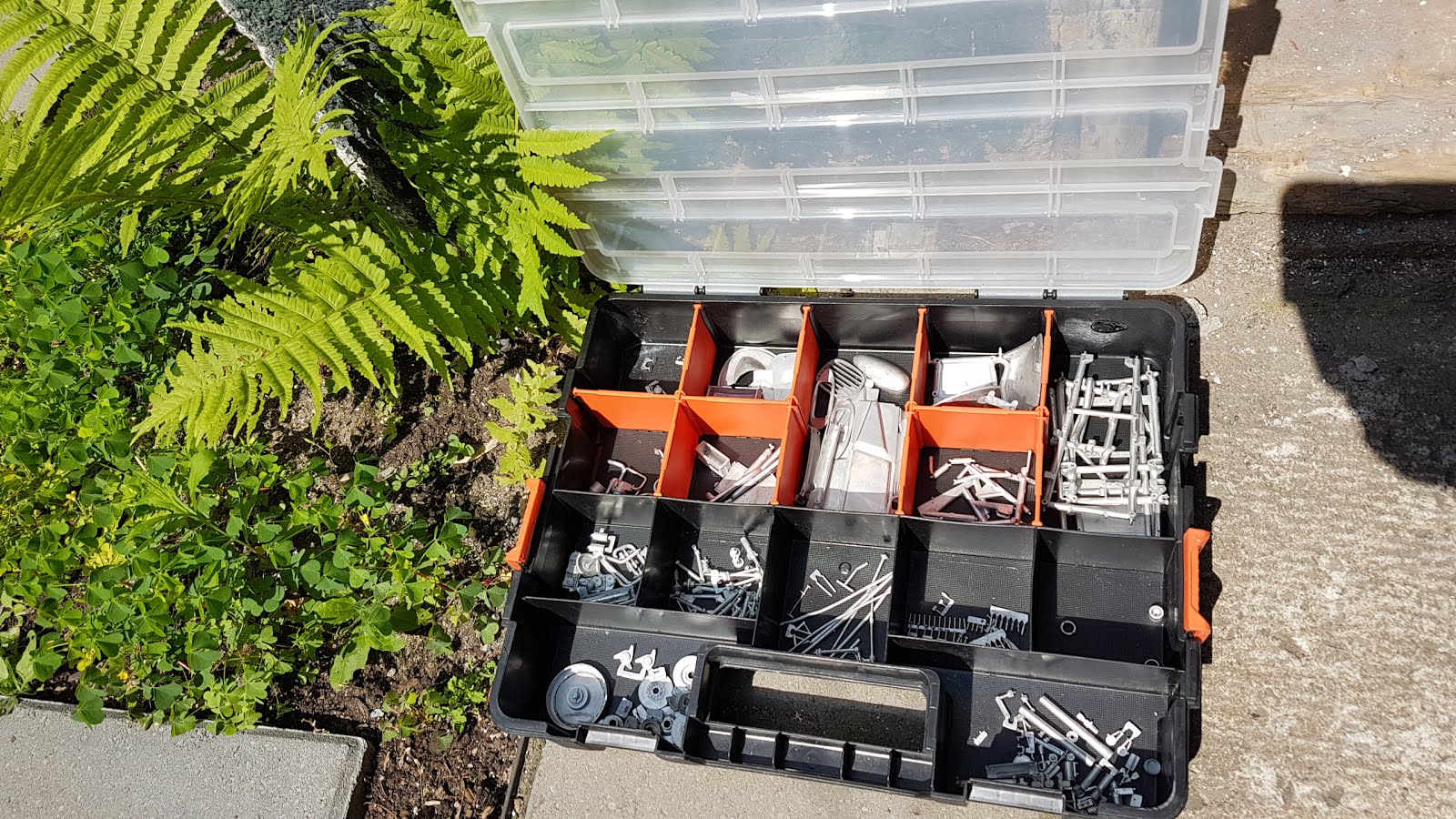
The first baggie, the biggest one, has a range of chassis bits. Lotus had monocoques by 1961, but Ferrari was sticking with the familiar tube frame. Fortunately these are nice and sturdy, unlike the 1:24 tube frames from MFH that I have assembled.


Sadly, the jig for lacing up the wheels is bent. I am told that MFH service is wonderful so I may try to get a new one.


Baggies 2 and 3 contain different bits related to bodywork and interior, as well as cam covers and exhaust pipes. After the spaghetti maze of the 908 and 917 exhaust systems, the simple V6 pipes are a joy.


More bent sheet but that is OK.


Baggie 4 is more engine bits along with brakes and suspension bits. There is also a large selection of 'bolts', some of which may get replaced by actual #00-80 bolts.


Baggie 5 has chassis struts, A-arms and an assortment of more or less bent tubes.


Baggie 6 has a mix of stuff, much of it unidentifiable at this stage. The battery is remarkable, being a 12V and a 6V battery wired up in series for 18V. I wonder what needed 18V in a 1961 GP car? The early version of the car had an additional 6V battery mounted immediately behind the dash. A fuel pump and a couple of magnetos ought to do it in my view, especially when dealing with the electrical needs of a carburetted 1.5 litre V6 making 190 hp. Then it occurred to me to have a good look through the manual: it appears there is no alternator to keep it all recharged. So the car gets a fresh battery on race day and off we go!


Finally Baggie 7, which I won't open just yet, is a load of little pins, rivets and other assorted connecting bits.


The little 120 degree V6 is made up of about 6 resin parts, plus the transmission. It's all on a sprue and looks almost like styrene. The 156 engine (meaning 1.5 litre, 6 cylinder) in previous years was a 65 degree unit; the new flatter engine for 1961 was balanced (which a 65 degree unit will never be) and could thus rev higher, as well as having a lower centre of gravity. Partly as a result of the new motor, and partly due to the driving of Phil Hill, the new car was unbeatable in 1961. The aluminum rims are just lovely and getting them straight will be a major operation, even with a straight jig.


All in all a classic shape. The kit does not, yet, appear to have much more detail than a 1:24 kit, so hopefully easier ... but the quality of final paint on the body will make or break it. Do I dare use Tamiya rattle cans? Stay tuned!

Monday, July 22, 2019

Lotus Elan S3: Final assembly Part I

Having put aside the Elan to build the MAZ, the MAZ is now on hold while putty sets. So back to the Elan.

The rubber gaskets around windshield and rear window were the deal breakers that led me to put it aside last time. I managed a so-so job, using a two-step approach:


First, I held the rubber in place in the corners using plastic clamps. Then I peeled back the gasket and applied crazy glue (yes, I am brave) to the groove along the top of the window and along the base of the window. Then I gently pressed the rubber into place with a #11 knife. (I use the medium speed, 5-15 second glue).


Second, I removed the clamps and pushed a little glue up inside the corners to keep it all from lifting.


Overall I was moderately successful; there's glue on the windows and a bit of paint damage to fix.


Finally I'll have a crack at the 0.3 mm aluminum rod used to model the chrome strip that wedges the gasket into place in real life, but I may decide to skip it. 0.3 mm is only 0.012" so quite flexible.

MAZ 537: Cab (again) and drivetrain (still)

The resin cab continues to be a problem. The first batch of primer covered the cab completely, but didn't stick; this second attempt, after stripping, cleaning in Purple Power and respraying, showed two spots where paint stuck the first time, but now wants to run from some sort of chemical contaminant. Argh. So it's back in the isopropyl bath (and beware: 24 h in isopropyl can make the resin soften up).


Meanwhile I have scratch built catwalks, exhaust system, a support for one of the two gas tanks in the kit, and a big roof-mounted scoop to feed the turbo. Sadly the scoop faces a bunch of hot air exhaust vents on the roof of the engine compartment rather than cool fresh air, but so be it.


I just need to route the wastegate outlet to the main exhaust pipe. The triple lake pipe came from Italeri's truck accessory kit. The main exhaust is painted Testor's Flat Rust which is a pretty poor imitation, frankly. I may need to redo this.


It's getting crowded back there, and it would be nice to have a duct leading down into the turbo inlet which otherwise is sucking from around the gas tank.


Just missing the breather on the forward valve cover, and the connection from the wastegate to the exhaust.


I saw somewhere on the Interweb that fuel consumption for this beast is 140 litres per 100 km, which is just about 14 times what my trusty Volvo, Thor, gets me. So having only one tank, and at a smaller scale at that, may be limiting, but I want to make sure there is nothing back of the 2nd steering axle to interfere with payload, so this may be it.


Here is the current state of the extended engine cover, fabricated using bits from the 1:35 winch housing and random bits left over from the 1:35 light tank which I cannibalised for my SSP (Super Snow Plough).


So the chassis is looking good, at least. I'll add a few other bits like a battery box from the Freightliner kit. Hopefully there will be a painted cab at some point.


Two steps forward, one back, which is better than two back, one forward. Just getting some additional putty on the roof before beginning final assembly. Stay tuned!

Sunday, July 7, 2019

MAZ 537: Cab and drivetrain

Some random progress over the last little while.

The cab now sports a three-tone paint job, marred by a couple of spots where the primer and all layers of paint on top of it have peeled off with the tape, in spite of leaving it all for over a week to settle.


I have had this problem with resin before and I'm not sure what is not working; I am sure that the Duplicolor primer sealer is a common item; maybe I need to reconsider this as my go-to base, or review my resin cleanup approaches. The Interweb insists that a tire bleaching chemical called Blechly (yes, really) is the ticket; one correspondent said Easy-Off would do the trick of getting rid of the mould release agents which are probably at the root of this.


With the cab painted, and while waiting to decide about stripping or patching the paint, I glued in the engine and the two deck plates either side of it.


With these fixed in place, I scratch built the piping to the intercooler. Bits of exhaust from the Cummins have been pinned together with 1/32" rod.


Deck plates came from the Italeri truck accessories kit.


With paint these are looking good. I have taken hose clamps from the spare PE drawer.


The cab is probably heading for the stripper, in part because I am not that happy with the paint colours.


Regardless of the paint scheme, the truck is really coming together, and the cab can be glued in at the last moment. Next will be the coolant radiator on the other side of the engine. The exhaust pipe will be finalised at a later date; I like the view of the compressor so I am probably going to skip the air filter. 


Stay tuned!