Saturday, May 31, 2025

Porsche 917/30: Front chassis

Front tubular chassis bits follow the usual excessively complex MFH approach. 

Progress was slow but steady. Making sure every little 0.5 mm socket is drilled out is critical.


The main flaw is the rack, which should have gone in earlier, is bent and the mounting pin i not quite entered into the left side socket. 


Front wheels are test-fitted and it all looks nice and square. 


Rear suspension and brakes also went on in order to get it sitting on all four as quickly as possible. 


The chassis is essentially complete and sits nice and square. The front clip fits nicely but some work will be needed to get the engine lid to sit on it properly. Stay tuned!  


Wednesday, May 7, 2025

Porsche 917/30: Rear chassis

The engine is now installed in the chassis and all the chassis tubing bits are done. This includes the turbocharger piping and a few other bits and bobs. This was all surprisingly easy compared to my recollections of the dreaded 908/03; and maybe this reflects the experience I've acquired in building 25 Model Factory Hiro kits since that 908/03, 17 of them at 1/24 scale. Time to dig out the 1971 version of 908/03 kit out of the stash, perhaps?


Next: front tub details, and rear suspension bits. Stay tuned!

Sunday, May 4, 2025

Porsche 917/30: Engine

This is my second MFH 917 motor at 1/24, third overall if you include the 908/03 which is quite similar. So I'm getting better at it knowing what to expect -- photo-etched throttle linkages and two plugs per cylinder among other things. The semi-transparent yellow plastic for the fibreglass bits is lovely. Here is the injector wiring going in, with injectors pointing up into the airstream, a first for me:


The engine is clearly wired up as a pair of 6-cylinder inline motors, where the cross-over exhaust piping in the 908 engine shows it was wired up as a pair of flat fours end to end.

First bank of wiring done. I used Detail Master 0.016" red plug wire for this, because the provided black wire is both too flimsy and too hard to see.

This is the hard side to do, with the injection pump in the way.


The other side (right side of the engine) has less stuff in the way of the plug wiring. 


Next: Plunk this all in the chassis where it will never be seen again. Stay tuned!


Wednesday, April 30, 2025

Porsche 917/30: Introduction

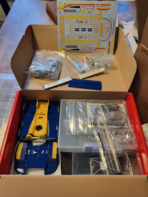
A Facebook colleague asked me to help him out with the devilishly complex 1/24 scale Model Factory Hiro kit of the devilishly complex Porsche 917/30 as driven by Mark Donohue. Specifically, the paint has been done, and the engine started; and as paint is my least favourite part of this hobby, I agreed. So the owner of the kit mailed it to me and it turned up about a week ago. 


First step was to disassemble the engine as I intend to paint and detail it, even if none of it will be visible once complete. I gently pried off the lovely semi-translucent fan shroud and tossed the rest into the acetone bath to dissolve the CA glue.


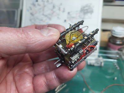
Then I got out my lovely new DC drill press and went to work with the 0.016" bit: 12 injectors, 12 injector ports on the injection pump, 24 spark plugs in the cylinder heads, 24 plug wires on the distributors, 4 coil wires on the distributors and 4 coils, all this without once breaking a bit or sliding off the part and driving the bit into my thumb. 

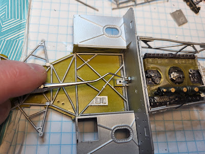
Reassembly is progressing. But I know from experience that it is wise to ensure the engine, rear tubular chassis and cockpit tub all line up as early as possible, otherwise you wind up wrestling with a complete but delicate engine, in a complete but delicate chassis, to get it all to line up. So I also got started on these other components.This involved sorting through piles of flexible and poorly formed 1 mm diameter white metal tubing. 


Eventually I got to the point of bolting the engine block and rear chassis to the cockpit tub, using a larger M2 stud and nut in place of the provided M1.4 x 3.0 screw. This shows that the rear engine mounts need to be moved forward about 2 mm, a good thing to know at this stage.


Stay tuned, this will only get better.


Monday, April 21, 2025

Ferrari 250 LM: Fitting the body

Well now. Perhaps I was getting a little cocky in thinking this was all going to go together like a breeze. A little too easy, perhaps, and I was lulled into a false sense of security by my arch-nemesis Murphy who targets me unceasingly in spite of my always giving him his due and doing all the necessary bowing and scraping. But I digress.


Turns out the rear engine lid doesn't line up with the rear valance (as shown below), in spite of a test fit prior to painting (as shown above) showing that it does. So possibly something is holding the body up, although it is hard to see what that might be. I also screwed up a decal (thank goodness for indycals.com) and broke one of the excessively flimsy hinges for said rear engine lid, so it was time to step away before I accidentally wound up heaving it out the window in a fit of frustration. 

So it's sitting on the Shelf of Doom until the decals arrive, and until I can suss out what went wrong. I'll also need to redesign the silly little hinge with something involving real metal. 

Meanwhile I am considering a stress-breaker in the form of a 1/24 kit. These big kits are lovely but this has been the only thing on the bench since mid-December. Stay tuned!

Tuesday, April 15, 2025

Ferrari 250 LM: Windshield

Well, now, this was different. Model Factory Hiro's 1/12 kit of the Ferrari 250 LM comes with an actual windshield rubber gasket and a length of wire to lock it into place. It also comes with a gasket for the rear window separating the cockpit from the engine bay, but that's simpler and less in your face once done.

Starting with the rear window, the photo shows the finished product which was relatively simple: glue the rubber to the body with Micro Kristal Klear, then force in the sheet of clear styrene cut to fit. A bit fiddly but it works. 


The windshield is a whole other story because the piece is so big and has to be cut carefully from the vacuum-formed sheet, and because the wire lock adds complexity. So I thought I should document this. First up is the instruction sheet. 


All very tidy and I started with the rubber gasket as described. I used Revell Contacta Clear contact cement along the inside, squooshing it up inside the gap with the body. Tape was used to keep it all in place while the glue set.. 


Then I cut out the windscreen, and used a file to sharpen the edges so it would slide into the slot in the rubber more effectively. I also used a toothpick to lubricate the rubber slot with Dawn dish soap. A lot of struggling ensued, possibly because I had cautiously cut the window a bit big, and the rubber eventually broke lose from its glue joint. 

There are no pictures of this event. 

Take 2 involved scraping off all the Contacta Clear and underlying paint from the inside of the cabin. This was pretty easy, the stuff scrapes off nicely taking the paint with it, and getting it off the rubber wasn't too onerous either. A new fit caused the rubber to settle into the lip in the body a little deeper, due to the paint removed; then I trimmed the window a bit. It turns out that I went a little overboard on the trimming, but I still managed to get the window to sit where it belongs, held in by Micro Kristal Klear (the white line in the photo; this dries clear after an hour or two). 


You can see the gap where the Micro Kristal Klear isn't quite filling the gap at the top of the left-side A pillar. I'll build that up with successive layers of Micro Kristal Klear over the next while.


On to the wire. The kit provides a length of soft aluminum wire (0.048" diameter) and a resin jig with which to bend it. 


Note that 0.0475" at 1/12 scale is 9/16" (14.3 mm) at full scale, and seems to me to be a bit big in terms of scale. Also (and more relevant to the discussion), I couldn't see forcing a wire that big into the gap in the rubber gasket without displacing said gasket, even in the context of the instructions showing the wire only going in to a depth about half its diameter. So I substituted some lead-free soldering wire (0.031") which is glued in only at the joint between the two ends under the clamp. It all seems to be holding... perhaps 1 mm wire (0.039") could have worked too.


Once it all sets, there will be some cleanup of the glass and maybe a very gentle polish as there are a few scratches to deal with. 

Oh and if you've read this far: put the windscreen in as soon as you are happy with the paint and decals, and before you join body to chassis. The instructions tell you to put it in once the body and chassis are mated, but this way lies madness. You'll never get your fat fingers up inside the cabin above the dashboard to hold it all in place. 

Stay tuned! I'll keep you posted.

Sunday, March 16, 2025

Ferrari 250 LM: Cockpit and forward chassis mated to the rear chassis and engine

The cockpit is essentially done. One nice touch is the rubber pieces that mimic the quilted interior. 


Front suspension is done, leaving just the brakes to do. 


One of the biggest challenges with these 1/12 scale Model Factory Hiro kits is mating the cockpit to the rear chassis and engine bay so that the result is straight and flat, and the body lines up properly. 


Lots of filing, bending and test-fitting before taking the plunge and getting out the 5-minute epoxy and my larger clamps. I'm committed now! 


 Next on to the body, which appears to be fairly flimsy requiring some internal reinforcing bits to be glued in. I suspect I should use the 5-minute epoxy here as well. Stay tuned!